background image

PRIMERGY BX600 S2 Basic Unit


7

Introduction

1

Introduction

The PRIMERGY BX600 S2 Blade Server System represents a highly compact, 
power-saving and scalable servers for integration in 19-inch rack systems.

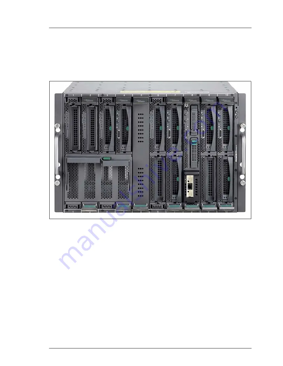
Figure 1: PRIMERGY BX600 S2 Basic Unit

The PRIMERGY BX600 S2 basic unit occupies seven height units in the rack 
and can accommodate up to ten server blades of different models and configu-
rations.

As economical, ultra-compact systems, the server blades with up to eight CPUs 
are ideal for use by company data centers and Internet service providers. They 
are perfectly suited for large application servers, terminal servers for CPU-
intensive applications, and DBMS servers.

The PRIMERGY BX600 S2 Blade Server System offers a high level of reliability 
and availability through highly developed hardware and software components. 
This includes hot-swappable server blades, switch blades, Fibre Channel (FC) 
and Ethernet pass-thru blades, management blades, hot-swappable power 
supply units and fan modules, the server management software 

ServerView

, and 

Remote-Deploy

, Prefailure Detection and Analyzing (PDA), and Automatic Server 

Reconfiguration and Restart (ASR&R).

Summary of Contents for PRIMERGY BX600 S2

Page 1: ...PRIMERGY BX600 S2 Basic Unit Operating Manual Edition March 2007 ...

Page 2: ...n was created to meet the regulations of a quality management system which complies with the requirements of the standard DIN EN ISO 9001 2000 cognitas Gesellschaft für Technik Dokumentation mbH www cognitas de Copyright and Trademarks cognitas Gesellschft für Technik Dokumentation mbH 2007 Pfad H windows _projekte Bxz Betriebsanleitung Version_Maerz 2007 Archiv BX600S2_en blade us vor Copyright 2...

Page 3: ...ate 25 3 4 FCC Class A Compliance Statement 26 3 5 Transporting the Basic Unit 27 3 6 Notes on Installing in the Rack 28 3 7 Environmental Protection 29 4 Installing the Hardware 33 4 1 Installation Steps 33 4 2 Unpacking the Basic Unit 34 4 3 Installing the System in the Rack 35 4 3 1 Mounting the Assembly Kit 38 4 3 2 Mounting Removing the Basic Unit 40 4 4 Connecting External Devices 41 4 4 1 C...

Page 4: ...m Components 60 5 4 1 Updating the Server Blade Firmware BIOS and BMC 60 5 4 2 Updating the Management Blade Firmware 62 5 4 3 Updating the Switch Blade Firmware 64 6 Property and Data Protection 69 6 1 BIOS Setup Security Functions 69 7 Server Blades 71 7 1 Installation Sequence 73 7 2 Adding a Server Blade to the Basic Unit 76 8 LAN Switch Blades 81 8 1 Gbit Ethernet LAN switch blade SB9 6x1Gbit...

Page 5: ...ort assignment 108 10 3 FC switch blade installation 111 11 Fibre Channel Pass Thru Blade 113 11 1 Control and Connection Panel 114 11 2 Fibre Channel SFP module 115 11 3 Port Assignment of the FC Pass Thru Blades 117 11 4 Exchanging an FC Pass Thru Blade 121 12 Management Blade 125 12 1 Control and Connection Panel 126 12 2 Exchanging the Battery 128 12 3 Exchanging a Management Blade 130 13 KVM ...

Page 6: ... the Fan Unit 151 15 1 2 Replacing a Fan in the Unit 153 16 Troubleshooting and Tips 155 16 1 System Power LED Remains Unlit 155 16 2 Front or Rear Identify Fault LED Blinks Amber 156 16 3 System Switches Itself OFF 157 16 4 Screen Remains Dark 157 16 5 Flickering Stripes on the Monitor Screen 158 16 6 No Screen Display or Display Drifts 158 16 7 No Mouse Pointer Displayed On the Screen 158 16 8 F...

Page 7: ...Us are ideal for use by company data centers and Internet service providers They are perfectly suited for large application servers terminal servers for CPU intensive applications and DBMS servers The PRIMERGY BX600 S2 Blade Server System offers a high level of reliability and availability through highly developed hardware and software components This includes hot swappable server blades switch bl...

Page 8: ...ling the hardware and operating the system The manual contains all the information required for mounting and operating your PRIMERGY BX600 S2 basic unit For a brief overview of the installation steps please see chapter 2 on page 19ff To understand the different expansion options you need a knowledge of hardware and data transmission as well as basic knowledge of the operating system used Additiona...

Page 9: ...Systems LAN Switch Blade User Interface Description PDF Version auf ServerBooks DVD enthalten PRIMERGY BX Blade Server Systems Cisco Catalyst Blade Switch 3040 Hardware Installation Guide PDF Version auf ServerBooks DVD enthalten PRIMERGY BX Blade Server Systems LAN Router and Switch Blade User Interface Description PDF Version auf ServerBooks DVD enthalten BX600 Digital KVM Switch User Guide PDF ...

Page 10: ...t types of communication blades which allow the installed server blades to be connected to the Ethernet LAN or to SAN environments The connections can be implemented via switch blades and or pass thru blades Ethernet LAN switch blade To connect the server blades to the LAN the following switch blade models are available Gbit Ethernet LAN switch blade SB9 6x1Gbit 10 internal 1Gbit downlink ports to...

Page 11: ...J45 connectors Fibre Channel pass thru blade The PRIMERGY BX600 S2 basic unit can have one or two Fibre Channel pass thru blades to provide Fibre Channel functionality for the installed server blades A Fibre Channel FC pass thru blade offers 10 ports for bypass connections between FC daughter cards installed in the server blades and the optical transceivers for serial FC I O and general I O signal...

Page 12: ...y config uration ensure enough power for the system If one of these units fails the others ensure that operation continues unimpaired The defective power supply unit can be replaced during operation hot swap Ventilation The system is kept cool by three fans in each power supply unit and four single fans with two of them mounted one after the other in a housing in the rear chassis This configuratio...

Page 13: ...e monitoring of the fans with timely notification before a failure Watchdog timer for operating system monitoring and application monitoring with ASR R Deployment software makes installing multiple servers fast and easy For further information see the corresponding documentation see Related Publications on page 165 Information on server management with ServerView is provided in the associated docu...

Page 14: ... for system analysis remote configuration and remote restart should the operating system or hardware fail 1 3 Notational Conventions The following notational conventions are used in this manual Italics indicate commands menu items or software programs Quotation marks indicate names of chapters and terms that should be emphasized Ê Text which follows this symbol describes activities that must be pe...

Page 15: ...ower 230 V 2650 W Max apparent power 2680 VA 230V Thermal dissipation 2050 kJ h Protection class I Power consumption 360 W Thermal dissipation 1300 kJ h Product safety and ergonomics IEC 60950 EN 60950 UL 1950 3rd Edition CSA 22 2 No 950 Electromagnetic compatibility FCC class A Emitted interference EN 55022 class A Harmonic current EN 61000 3 2 Noise immunity EN 55024 CE label according to EU dir...

Page 16: ...ntation mbH 2007 Pfad H windows _projekte Bxz Betriebsanleitung Version_Maerz 2007 Archiv BX600S2_en blade us k01 Mechanical Values Weight max 131 5 kg depending on the configuration Europe ENEC Germany GS USA Canada CSAUS CSAC Japan VCCI Width 446 mm Installation depth 740 mm Height 307 mm oder 7 HE ...

Page 17: ...oided Noise Level Environment class 3K2 Environment class 2K2 DIN IEC 721 section 3 3 DIN IEC 721section 3 2 Temperature Operation 3K2 Transport 2K2 5 ºC 35 ºC 20 C 60 C Relative humidity 10 85 Sound power level LWAd ISO 7779 7 8 BA Sound pressure level at bystander position LpAm ISO 9296 59 dB A in the standard configuration ...

Page 18: ... cognitas Gesellschft für Technik Dokumentation mbH 2007 Pfad H windows _projekte Bxz Betriebsanleitung Version_Maerz 2007 Archiv BX600S2_en blade us k01 ...

Page 19: ...on Cable Routing on page 43 and the section Instructions on Connecting and Disconnecting Cables on page 45 Ê Connect the system to the mains voltage see section 4 5 on page 46 Ê Familiarize yourself with the operating and indicator elements on the front and rear sides of the BX600 S2 basic unit see chapter 5 beginning on page 49 Ê Insert the server blades into the slots in the front of the BX600 S...

Page 20: ...lation or cloning are not satisfied If you wish to install an operating system that is not supported by Server Start you can perform the installation directly without using ServerStart I For further information on remote or local installation of server blades please see the ServerStart manual which contains a Quick Step Guide as well as a detailed description of the different installation options ...

Page 21: ...chines for use in an office environment If you have any questions please contact your sales outlet or the customer service center of Fujitsu Siemens Computers V CAUTION The actions described in these instructions should only be performed by technicians service personnel or technical specialists Equipment repairs should only be performed by qualified staff Any failure to observe the guidelines in t...

Page 22: ...l packaging or in packaging which protects it from knocks and jolts Installation and Operation V CAUTION For safety reasons make sure you read any warning labels when removing modules from the server Beware of energy hazards on the plug in contacts of the midplane A short circuit on these connections can lead to damage to the system PRIMERGY BX620 S4 server blades are not for use in slots 4 an 10 ...

Page 23: ...k of electric shock or short circuit Data cables must be adequately shielded to avoid interference The LAN wiring must comply with the standards EN 50173 and EN 50174 1 2 The minimum requirement is a protected LAN line of category 5 for 10 100 MBps Ethernet and or of category 5e for Gigabit Ethernet The requirements of the specification ISO IEC 11801 must be observed In an emergency e g damage to ...

Page 24: ...Technical data section of the monitor description Otherwise you may damage your monitor If you are in any doubt contact your sales outlet or customer service center Batteries V CAUTION Incorrect replacement of batteries may lead to a risk of explosion The battery may only be replaced with an identical battery or with a type recommended by the manufacturer Do not throw batteries into the trash can ...

Page 25: ... charge Always hold components with ESDs by their edges Do not touch any exposed pins or conductors on a component Use a grounding cable designed for this purpose to connect yourself to the system unit as you install components Place all components on a static proof base I You will find a detailed description of how to handle ESD components in the relevant European or international standards EN 61...

Page 26: ...rmful interference to radio communications However there is no guarantee that inter ference will not occur in a particular installation If this equipment does cause harmful interference to radio or television reception which can be determined by turning the equipment off and on the user is encouraged to try to correct the interference by one or more of the following measures Reorient or relocate t...

Page 27: ...the basic unit until you have finished transporting it For safety reasons at least two people are needed to install the basic unit because of its weight and size Before lifting the basic unit into the rack remove server blades fan units and power supplies from the system unit to reduce weight Use the handles on the front and the fold away handles on the long sides to lift or carry the base unit Ne...

Page 28: ... the rear For safety reasons only one unit may be withdrawn from the rack at a time when performing assembly or service work Ensure that the anti tilt bracket is correctly mounted when you set up the rack If more than one unit is withdrawn from the rack at any one time the rack is in danger of tilting forward When connecting and disconnecting cables read the relevant notes in the Important notes c...

Page 29: ...ices that do not have to be on permanently should not be switched on until they need to be used and should be switched off during long breaks and on completion of work Notes on Packaging Please do not throw away the packaging It may be needed later for transporting your system unit If possible devices should be transported in their original packaging Notes on Dealing with Consumables Please dispos...

Page 30: ...our used device please use the country specific return and collection systems available to you see Local Contacts on page 31 The return of used devices which pose a health or safety risk for human beings due to soiling during use may be refused Reuse recycling and utilisation By actively using the offered return and collection systems you make your contribution to the reuse recycling and utilisati...

Page 31: ...he following applies to Germany Private consumers can return batteries at the point of sale or the immediate vicinity thereof free of charge exception starter batteries The final consumer is obligated to return defective or used batteries to the seller or to the return points established for this purpose Local Contacts For details on take back and reuse of devices and consumables within Europe con...

Page 32: ... cognitas Gesellschft für Technik Dokumentation mbH 2007 Pfad H windows _projekte Bxz Betriebsanleitung Version_Maerz 2007 Archiv BX600S2_en blade us k03 ...

Page 33: ...steps are described in detail in the following sections of this chapter Unpacking the basic unit see section Unpacking the Basic Unit on page 34 Mounting the basic unit in the rack see section Installing the System in the Rack on page 35 and also the layout arrangement on the order lists Cabling the basic unit see section Connecting External Devices on page 41 See also the section Cable Routing on...

Page 34: ...BX600 S2 basic unit until you have finished transporting it We recommend that you do not throw away the original packaging material It may be required for future transportation Ê Unpack all the individual parts Ê Check the contents of the package for visible transport damage Ê Check whether the delivery matches the details in the delivery note The identification rating plate is located on the fron...

Page 35: ...rack fully support the installation of the PRIMERGY server systems Installation in the common rack systems of other manufacturers 3rd party rack is supported to a large degree To accommodate the ventilation concept and ensure proper ventilation of the components in the rack any unused areas must be closed using dummy covers The unit is connected to the power supply via an external distribution boa...

Page 36: ...s No support for the cable management delivered with the mounting kit This cable management is customized for the Fujitsu Siemens Computers PRIMECENTER rack Climatic conditions For the ventilation of the installed server there must be sufficiently large gaps for air intake at the front of the rack and air discharge at the back of the rack 1 rack front 2 rack rear A rack depth comparison PRIMECENTE...

Page 37: ...ciple the ventilation concept allows for the necessary cooling through horizontal self ventilation of the installed devices air flow from the front to the rear Power supply For installation in 3rd party racks you must ensure that appropriate socket strips are present Figure 5 Mechanical conditions ...

Page 38: ...ust first mount two support brackets on the rear left support upright of the rack The first one must be mounted level with the lower edge of the device while the second must be mounted level with the upper edge of the first The brackets are used for the rear fixing of the left carrier rail Ê See the installation instructions in the technical manual for the relevant rack model Ê Mark the position o...

Page 39: ...s of the support brackets Ê Place three plug washers 3 in the appropriate holes of the support brackets and while holding the rail in place fasten it with three screws Ê Place two plug washers in the holes of the front left support upright at the marked attachment points adjust the rail length 2 and while holding the rail in place fasten it with three screws 4 Ê Pull the carrier rail of the rack m...

Page 40: ...e lifting the basic unit into the rack remove server blades fan units and power supplies from the basic unit to reduce weight Figure 8 Mounting the basic unit Ê Note the slot assignment of the server blades so that you can insert them correctly again once you have lifted the basic unit into the rack Ê Remove server blades fan units and power supplies from the system unit to reduce weight for assem...

Page 41: ...g in the Rack on page 28 Ê Note the slot assignment of the server blades so that you can insert them correctly again after you have removed the basic unit from the rack Ê Remove server blades fan units and power supplies from the basic unit to reduce weight Ê Remove the four knurled screws Ê Pull out the basic unit and carefully remove it from the rack 4 4 Connecting External Devices The external ...

Page 42: ...witch blades or pass thru blades see Ethernet LAN Switch Blades on page 81 Ethernet Pass Thru Blade on page 99 Fibre Channel Switch Blade on page 105 and Fibre Channel Pass Thru Blade on page 113 3 Serial port connector on management blade 2 see also figure 53 on page 100 Standard serial port management communication port 4 LAN connector on management blade 2 see also figure 53 on page 100 LAN por...

Page 43: ...nt If a PCI expansion module is installed in a server blade you will have to connect the PCI port with an external device on the back of the rack To route the cable from the front to the back of the rack use the side slots of the rack with a cable bezel as shown in figure 11 below You may also route the cable to the back of the rack using the space below the basic unit VGA mouse green keyboard pur...

Page 44: ... 11 Cable routing from the front to the back of the server top view Server blades with SCSI boards installed via PCI expansion modules can only be installed in slots 5 and 6 of the basic unit This is why about 100 mm of space is required in front of the server due to the bend radius of the SCSI cable The curved design of the PRIMECENTER rack door ensures that there is sufficient room for slots 5 a...

Page 45: ...nt switches Ê Pull all power plugs out of grounded power sockets or CEE sockets Ê Plug all cables into the system and peripherals Secure the data trans mission cable connections e g nut retention Ê Plug all data communication cables into the utility sockets Ê Plug all power cables into the grounded power sockets or CEE sockets Disconnecting Cables Ê Turn off all power and equipment switches Ê Pull...

Page 46: ...h on automatically at a mains voltage between 200 240 V The base unit may only be commissioned if the local mains voltage is within the voltage range of the system The 2100 W power supply units may only be connected to 16 Amp grounding outlets or CEE outlets When ordering the base unit indicate the type of outlet available at the installation site This will allow us to supply a cable with suitable...

Page 47: ...one phase has failed the power supply units connected to the other phases keep active You can get full phase redundancy with up to three power supply units With four power supply units two of them are to be connected to one phase see also Related Publications on page 165 Phase redundancy is possible in regions where a single phase provides 200 240V in other regions with lower single phase voltage ...

Page 48: ... cognitas Gesellschft für Technik Dokumentation mbH 2007 Pfad H windows _projekte Bxz Betriebsanleitung Version_Maerz 2007 Archiv BX600S2_en blade us k04 ...

Page 49: ...ergy hazards on the plug in contacts of the midplane A short circuit on these connections can lead to damage to the system All unoccupied component slots are fitted with corresponding dummy modules to ensure that the electromagnetic emission properties of the system are observed and that the system components are cooled properly Figure 14 PRIMERGY BX600 S2 basic unit ...

Page 50: ...m operating and indicator elements on the front 1 Power indicator bicolor LED Lights amber basic unit is ready for powering ON 5 V standby power present Lights green basic unit is switched ON 2 System power ON OFF button When the basic unit is switched OFF pressing the power button for 2 seconds will switch it ON When the basic unit is operating and the button is kept pressed for 4 seconds the bas...

Page 51: ...ent Lights amber This system has been selected by pressing the front or rear identify button To deactivate press one of the buttons again You also can activate the LED via CLI Blinks amber The system is directly controlled via the management blade user interface or SUM error A malfunction has occurred in the system 4 Front identify button Pressing this button lights up the integrated front identif...

Page 52: ...ton lights up the rear identify indicator The front and rear identify indicators will be synchronized 1 Figure 16 shows the operator panel of the standard KVM blade For further information on this KVM blade and on the adv KVM blade see chapter KVM Blade on page 133 2 Rear identify Fault indicator green LED 1 Lights green This system has been selected for identification identify LED is lit by press...

Page 53: ...basic unit power ON OFF button position 2 in figure 15 on page 50 for 2 seconds Depending on the BIOS settings the server blades can be switched on automatically one after another according to the slot numbering see figure 29 on page 72 Ê If necessary switch ON the required server blades see Switching the Server Blades ON OFF on page 54 The basic unit is switched ON and the activated server blades...

Page 54: ... operating before the power failure are booted automatically Switching the Server Blades ON OFF The basic unit must be powered ON The server blade can be switched ON and OFF in the following ways To switch ON the server blade press the power button of the server blade see the manual for the relevant server blade type To switch OFF the server blade press the power button of the server blade see the...

Page 55: ...uter To configure the management blade follow the steps listed below Pre Configuration Requirements The procedures that follow assume that the basic unit is connected to the power line Cabling the System Ê Connect the serial interface of the client COM1 to the serial interface of the master management blade using an RS232 cable null modem cable I The master management blade is indicated by a green...

Page 56: ...he console menu will be displayed see figure 17 below Figure 17 Welcome screen Ê Log in as root The initial password reads root V CAUTION Change the root password as soon as possible see page 56 Failure to do so may result in unauthorized access and loss of customer data I You can change the root password of the management blade via menu item 6 Username and Password of the Management Agent menu se...

Page 57: ...uration Ê Enter 1 to call up the Management Agent menu The Management Agent menu looks like this Figure 19 Management Agent menu Ê Enter 1 to call up the Management Agent Information menu The Management Agent Information menu provides access to the parameters required by the LAN connection ...

Page 58: ...anleitung Version_Maerz 2007 Archiv BX600S2_en blade us k05 Figure 20 Management Agent Information menu Follow the steps below to make the management blade accessible via the LAN Ê Select 1 to set the IP address of the management blade Ê Select 2 to enter the network mask of your subnet Ê Select 3 to enter the IP address of your gateway Ê Select 18 to call up the Agent NTC Duplex Mode menu ...

Page 59: ...er 0 in this menu and in the preceding menus to leave the management blade console menu Ê Close the HyperTerminal session Ê Unplug the power cable from the basic unit and plug it in again to reboot the management blade I This ensures that the management blade continues to act as the master after the restart A restart without interruption to the power supply would cause the master slave assignment ...

Page 60: ...rver blade BIOS and the server blade BMC Updating the server blade firmware from a USB floppy drive This procedure is described in the Operating Manual for the server blade see Related Publications on page 165 Updating the firmware of the server blade with TFTP see below Proceed as follows Ê Install your TFTP server software and start it Ê Download the TFTP update package BX600 S2_TFTP IMAGES_ ver...

Page 61: ...ting the server blade BIOS via the web interface Ê In the TFTP Server IP Address field enter the IP address of the TFTP server which provides the BIOS image file for the server blade firmware Ê In the Boot Image File Name field enter the file name of the boot image file for the server blade Ê Use the Add and Delete buttons to select the server blades whose BIOS is to be updated Ê Click the Apply b...

Page 62: ...stall your TFTP server software and start it Copy the relevant firmware file bin to the root directory of the TFTP file system Ê Check the LAN connection by pinging the relevant management blade Ê Enter the IP address of the TFTP server which provides the BMC image file for the management blade firmware Enter the path and the file name of the image file for the management blade You have two option...

Page 63: ...you can enter any IP address that is not used in the LAN segment of the server Ê In the Boot Image File Name field enter the name of the image file of the management blade Ê Set the value of the TFTP Update Enable field to enable Ê Click Apply The firmware of the first management blade Master will now be updated the green LED lights up When the update process is complete this management blade is d...

Page 64: ...Switch on the basic unit and start the management console Telnet of the management blade Console Menu page_root 1 Management Agent 2 Emergency Management Port 3 Console Redirection 4 TFTP upgrade 5 Logout 6 Reboot Management Blade 7 System Information Dump Enter Selection 3 Ê In the management blade console select the menu item Console Redirection Console Redirection Table page_0 1 Console Redirec...

Page 65: ...config Console config interface vlan 1 Console config if ip address 10 50 50 51 255 0 0 0 Console config if exit Console show ip interface TP address and netmask 10 50 50 51 255 0 0 0 on VLAN 1 and address mode User specified Console Ê Enter the commands specified above I The specifications for the IP address and the subnet mask are merely examples and are probably not valid for your system Ê Term...

Page 66: ...r the user name and password admin The home page is displayed Ê In the navigation bar choose Flash File I Only two operation code image files can be stored on the switch blade If there are already two image files stored you must remove at least one of them before updating the firmware It is recommended that you remove the older file i e the file with the lower number Ê Expand the File Name list re...

Page 67: ... Refresh the browser for viewing Ê Select the new image file in the pop up window red arrow and click Apply Changes Figure 27 Selecting Start Up Operation Code Image File Ê Select Reset in the navigation bar I After resetting the switch blade will reboot However all settings specified previously IP address etc will be lost and must be reentered on the management console Ê Repeat the firmware updat...

Page 68: ... cognitas Gesellschft für Technik Dokumentation mbH 2007 Pfad H windows _projekte Bxz Betriebsanleitung Version_Maerz 2007 Archiv BX600S2_en blade us k05 ...

Page 69: ...ions you can achieve optimum protection for the system I A detailed description of the Security menu and how to assign passwords can be found in the manual for the BIOS Setup and on the ServerBooks CD see also Related Publications on page 165 Preventing Unauthorized BIOS Setup Calls This protection mechanism can be activated by setting a supervisor password in the Security menu In addition the Pre...

Page 70: ... cognitas Gesellschft für Technik Dokumentation mbH 2007 Pfad H windows _projekte Bxz Betriebsanleitung Version_Maerz 2007 Archiv BX600S2_en blade us k06 ...

Page 71: ...to be aware of when doing this The information necessary for installing and operating the various server blade models can be found in separate manuals see Related Publications on page 165 When you install a server blade in the basic unit an important factor is the height Figure 28 shows a 2 way server blade which occupies one slot in the basic unit Figure 28 PRIMERGY BX620 S3 S4 2 way server blade...

Page 72: ... Technik Dokumentation mbH 2007 Pfad H windows _projekte Bxz Betriebsanleitung Version_Maerz 2007 Archiv BX600S2_en blade us k07 The 4 way server blade is twice the height and occupies two slots figure 29 Figure 29 PRIMERGY BX630 scalable server blade 4 way configuration ...

Page 73: ... infrastructure modules on the back of the BX600 S2 basic unit via the midplane of the BX600 S2 basic unit Switch blade s Fibre Channel pass thru blade s optional Ethernet pass thru blade s optional Management blade s KVM blade Power supply units V CAUTION PRIMERGY BX620 S4 server blades are not for use in slots 4 an 10 of the PRIMERGY BX600 S2 basic unit In a PRIMERGY BX600 S2 basic unit differen...

Page 74: ...es or 4 way server blades or a mix of the two and how the server blades are equipped Configuration Diagram for 2 way Server Blades Slot 4 is filled first Next slots 5 through 10 are filled in numerical order followed by slots 1 through 3 2 way server blades with SCSI controller in a PCI extension module can only be installed in slots 5 and 6 because of the cabling arrangement in the rack see secti...

Page 75: ...of 2 way and 4 way Server Blades The 4 way server blades are fitted first followed by the 4 way server blades Begin with a 4 way server blade in slots 3 and 4 Figure 33 Installation sequence for three 2 way and three 4 way server blades I 2 way server blades with SCSI controller can only be fitted in slots 5 and 6 If only one 2 way server blade with SCSI controller is to be fitted it must go in sl...

Page 76: ... in slots 5 and 6 Figure 34 Installation sequence for an 8 way two 4 way and two 2 way server blades 7 2 Adding a Server Blade to the Basic Unit Depending on the desired configuration the system can be upgraded with up to 10 server blades V CAUTION Read the safety information and the information on handling electro static sensitive components in the section Components With Electrostatic Sensitive ...

Page 77: ... ejecting handles of the dummy module will be disengaged Ê Swing up the upper handle and swing down the lower handle simultaneously 2 until the locking mechanism of the dummy module disengages and the dummy module ejects Ê Remove the dummy module completely from the slot 3 V CAUTION Keep the dummy module for future use If the server blade is removed and not replaced with a new server blade then th...

Page 78: ...ts in the section Components With Electro static Sensitive Devices on page 25 Figure 36 Turning the eject handles into the unlocked position 2 way server blade Ê Press the touch points on the inside of the eject handles 1 of the server blade to disengage the locking mechanism of the handles Ê Turn the eject handles outward 2 into the unlocked position The 4 way server blade has the same locking me...

Page 79: ...igure 38 Inserting the server blade Ê Push the server blade into the slot as far as possible while keeping the eject handles in the unlocked position I Please make sure you install the server blade in the right direction The upper narrow side of the server blade is marked TOP SIDE 1 1 ...

Page 80: ...locking mechanism to engage fully Removing the Server Blade The server blade is removed in the same way as the dummy module see Removing the Dummy Module on page 76 V CAUTION Read the safety information and the information on handling electro static sensitive components in the section Components With Electro static Sensitive Devices on page 25 When you remove the server blade and do not replace it...

Page 81: ...pter also describes the port assignment to the server blades and how to install and uninstall the switch blades in the basic unit The information necessary for configuring and operating the various switch blade models can be found in separate manuals see Related Publications on page 165 The following switch blade models are available Gbit Ethernet LAN Switch Blade SB9 6x1Gbit Gbit Ethernet LAN Swi...

Page 82: ...s the following connections 10 internal 1Gbit downlink ports to the server blades 6 external 1Gbit uplink ports via RJ45 connectors Operating and Indicator Elements Figure 40 Gbit Ethernet LAN switch blade SB9 6x1Gbit 1 6 1 Gbit uplink LAN connectors with two integrated LAN status LEDs each LED A LAN active indicator bicolor LED Glows amber Port link at 1 Gbit s Glows green Port link at 100 Mbit s...

Page 83: ... can be found in the manual PRIMERGY BX Blade Server Systems LAN Router and Switch Blade User Interface Description see Related Publications on page 165 7 Power and system indicators green LEDs P Power indicator green LED Glows green Power enabled Dark Power disabled S System indicator green LED Glows green Selected for identification by the management blade Blinks green Error occured ...

Page 84: ... 6 external 1Gbit uplink ports via RJ45 connectors 2 external 10 Gbit uplink ports via XFP module and corresponding fibre optic cable and CX4 connector and corresponding copper cable Operating and Indicator Elements Figure 41 Gbit Ethernet LAN switch blade SB9 6x1 Gbit 2x10 Gbit 1 6 1 Gbit uplink LAN connectors with two integrated LAN status LEDs each LED A LAN active indicator bicolor LED Glows a...

Page 85: ...ace Description see Related Publications on page 165 9 Power system and 10 GbE status indicators green LEDs P Power indicator green LED Glows green Power enabled Dark Power disabled S System indicator green LED Glows green The switch has been selected for identification by the management blade Blinks green Error occured C CX4 link active indicator green LED Glows green CX4 network link Blinks gree...

Page 86: ...ports 4 external small form factor pluggable SFP module uplink ports that support 1000BASE SX fiber and 10 100 1000BASE T copper only Cisco SFP modules are supported Operating and Indicator Elements Figure 42 Cisco Catalyst Blade Switch 3040 1 Console port 2 Console port indicator bicolor LED Dark The bootloader is initializing Glows green The blade switch console port is active Glows amber The bl...

Page 87: ...hernet ports 5 Gigabit Ethernet port indicators bicolor LEDs Dark No link established Glows green Link established but no activity Blinks green Traffic on an established link Glows amber Port disabled either error or STP1 disabled Glows green or amber Link fault 6 SFP module ports 7 SFP module port indicators bicolor LEDs Dark No link established Glows green Link established but no activity Blinks...

Page 88: ...ir associated I O devices The 10 Gbit switch blade 10 2 provides the following features 10 internal 10 Gbit s ports to the server blades 2 external 10 Gbit s ports with optional X2 transceiver modules for Fiber optical or CX4 copper cable 1 console port V CAUTION You may install 10 Gbit switch blades 10 2 only in slots NET3 and NET4 of the basic unit see figure Slots for the switch blades on page ...

Page 89: ...ws CX4 link established Blinks CX4 link active 3 4 CX4 ports 5 Console port link indicator green LED Glows Link available 6 Console port active indicator amber LED Dark 1 Gbit s link available Glows 100 Mbit s link available Blinks Link active 7 Power indicator amber LED Dark Power enabled Glows Power disabled 8 ID indicator green LED Glows Switch blade is operating Blinks The switch blade has bee...

Page 90: ... switch blade in slot NET2 is connected to port B of the onboard LAN controller In the same way the LAN switch blades in slots NET3 and NET4 are connected to port A and B of the gigabit Ethernet daughter cards Figure 44 Slots for the switch blades The installation of two LAN switch blades in NET1 and NET2 or NET3 and NET4 enables redundant LAN connections to be provided for the relevant LAN contro...

Page 91: ...in slots NET3 and NET4 takes place accordingly Configuration with Ten 2 way Server Blades The following figure illustrates the assignment of the switch blades to the LAN ports of the server blades in a configuration with ten 2 way server blades Figure 45 LAN port assignment with ten 2 way server blades Server blade 8 Server blade 9 Server blade 10 Server blade 1 Server blade 2 Server blade 3 Serve...

Page 92: ...X600S2_en blade us k08 Configuration with Five 4 way Server Blades The following figure illustrates the assignment of the switch blades to the LAN ports of the server blades in a configuration with five 4 way server blades Figure 46 LAN port assignment with five 4 way server blades Server A B A B A B A B A B A B A B A B A B A B Switch blade 1 Switch blade 2 blade 5 Server blade 1 Server blade 2 Se...

Page 93: ...LAN Switch Blade Depending on the desired configuration the system can be upgraded with one additional switch blade V CAUTION Read the safety information and the information on handling electro static sensitive components in the section Components With Electrostatic Sensitive Devices on page 25 LAN switch blades must always be installed in slots NET1 and NET3 first see page 90 2 way A B A B A B A ...

Page 94: ...re fitted with dummy modules to ensure that the electromagnetic emission properties of the system are observed and that the system components are properly cooled If you wish to install a LAN switch blade you must first remove the dummy module from the corresponding slot Figure 48 Removing the dummy module a green touch point Ê Press the spring 1 on the underside of the handle a to unlock it Ê Swin...

Page 95: ... LAN switch blade and do not replace it with a new one you must reinstall the dummy module Installation is the same as for the LAN switch blade see Inserting the LAN Switch Blade on page 95 Inserting the LAN Switch Blade V CAUTION Read the safety information and the information on handling electro static sensitive components in the section Components With Electro static Sensitive Devices on page 2...

Page 96: ...S2_en blade us k08 Figure 50 Disengaging the switch blade Ê Disengage the locking mechanism of the LAN switch blade by swinging the handle in the direction of the arrow Figure 51 Inserting the switch blade a green touch point Ê Push 1 the LAN switch blade as far as possible into the desired slot here slot 2 Ê Swing up 2 the eject handle a of the switch blade until the locking mechanism of the LAN ...

Page 97: ... and the information on handling electro static sensitive components in the section Components With Electro static Sensitive Devices on page 25 If you remove the LAN switch blade and do not replace it with a new one you must insert a dummy module in the empty slot to ensure cooling to comply with the applicable EMC regulations regulations on electromagnetic compatibility and for fire protection Ma...

Page 98: ... cognitas Gesellschft für Technik Dokumentation mbH 2007 Pfad H windows _projekte Bxz Betriebsanleitung Version_Maerz 2007 Archiv BX600S2_en blade us k08 ...

Page 99: ...unit offers slots for up to four Ethernet LAN Pass Thru Blades on the back see figure 54 on page 101 Depending on the specific slot an Ethernet LAN Pass Thru Blade establishes connections to the onboard LAN controllers or to the optional Gigabit Ethernet I O modules daughter cards of the server blades For information on the optional Gigabit Ethernet I O modules daughter cards see the operating gui...

Page 100: ...nection panel of the Ethernet LAN Pass Thru Blade The following display and control elements are available 1 10 RJ45 connectors The RJ45 connectors are assigned to the server blades in accordance with their numbering for server blade slot numbering see figure 30 on page 73 a LAN activity indicator orange LED Blinks amber Active LAN connection Dark Inactive LAN connection b LAN connection indicator...

Page 101: ...s for installing pass thru blades The installation of two Ethernet LAN Pass Thru Blades in NET1 and NET2 or NET3 and NET4 enables redundant LAN connections to be provided for the relevant LAN controllers of the server blades V CAUTION Components must always be installed in slots NET1 and NET3 first This ensures that port A of the relevant LAN controller is connected if redundant LAN connections ar...

Page 102: ...onboard LAN controllers of the server blades The following figure shows the port assignment in a configuration with ten 2 way server blades Figure 55 Ethernet port assignment with ten 2 way server blades The Ethernet LAN Pass Thru Blades in slots NET3 and NET4 provide connec tions to channels A and B of the optional Gigabit Ethernet I O modules The ports in a configuration with ten 2 way server bl...

Page 103: ...Blades in slots NET1 and NET2 provide connec tions to channels A and B of the onboard LAN controllers of the server blades The following figure shows the port assignment in a configuration with five 4 way server blades Figure 56 Port assignment to the onboard LAN controllers with five 4 way server blades Server A B A B A B A B A B A B A B A B A B A B blade 1 Server blade 2 Server blade 3 Server bl...

Page 104: ... to the Gigabit Ethernet I O modules with five 4 way server blades 9 3 Replacing an Ethernet Pass Thru Blade V CAUTION Ethernet pass thru blades must always be installed in slots NET1 and NET3 first see page 101 An Ethernet LAN Pass Thru Blade is installed and removed in the same way as a LAN switch blade see section Installing a LAN Switch Blade on page 93 Server A B A B A B A B A B A B A B A B A...

Page 105: ...ade across a LAN I All features of Brocade Fabric OS 5 0 4 the joint software platform for Brocade fibre channel switches are available as an operating system for the FC switch blade Administration of the FC switch blade is handled by Fabric Watch and Advanced Web Tools from Brocade Figure 58 Fibre Channel Switch Blade I Besides the 16 ports version the switch blade unit is available as a 12 ports...

Page 106: ...2 RJ45 LAN connection with two integrated status LEDs see items 6 and 7 3 FC switch blade voltage status display green LED lights up when the base unit is switched on 12 V input voltage present 4 FC switch blade status display 2 color LED Dark FC switch blade is not operating Lights green FC switch blade is operating Lights amber Boot phase one or more ports are off line Blinks amber green Warning...

Page 107: ...able Blinks Data transport 8 Status display of ext FC ports 2 color LED Dark No signal reception Flickers green FC port on line data transport Blinks green slow FC port on line but segmented fast internal loop Lights amber Signal reception but not on line Blinks amber slow 2 sec intervals FC port disabled fast 0 5 sec interval FC port faulty 9 Speed display of ext FC port 2 color LED Dark FC trans...

Page 108: ... to port B of the installed fibre channel daughter cards Figure 60 Slots for FC switch blades The installation of two FC switch blades enables redundant fibre channel connections to be provided for the server blades V CAUTION FC switch blades must always be installed in slot NET3 first This ensures that port A of the FC daughter cards is connected if redundant fibre channel connections are not use...

Page 109: ... with ten 2 way server blades Figure 61 Fabric port assignment with 2 way server blades I When using the 12 port version the fabric ports of the server blades 6 and 7 slots 9 and 10 are not available Server blade 8 Server blade 9 Server blade 10 Server blade 1 Server blade 2 Server blade 3 Server blade 4 Server blade 5 Server blade 6 Server blade 7 A B A B A B A B A B A B A B A B A B A B FC switch...

Page 110: ...llustration below shows the assignment of FC switch blades to the fabric ports of the server blades in a configuration with five 4 way server blades Figure 62 Fabric port assignment with five 4 way server blades I When using the 12 port version the fabric ports of server blade 4 slots 9 and 10 are not available Server A B A B A B A B A B A B A B A B A B A B FC switch blade NET3 FC switch blade NET...

Page 111: ...ng the 12 port version the fabric ports of the 2 way server blades 3 and 4 slots 9 and 10 are not available 10 3 FC switch blade installation V CAUTION FC switch blades must always be installed in slot NET3 first see page 108 The installation and removal of FC switch blades takes place in the same way as the installation of fibre channel pass thru blades see page 121 2 way A B A B A B A B A B A B ...

Page 112: ... cognitas Gesellschft für Technik Dokumentation mbH 2007 Pfad H windows _projekte Bxz Betriebsanleitung Version_Maerz 2007 Archiv BX600S2_en blade us k09 ...

Page 113: ...el speed It also provides LEDs for each FC port to indicate the link status Figure 64 Fibre Channel pass thru blade The PRIMERGY BX600 S2 basic unit can be fitted with one or two FC pass thru blades The slots for these blades are on the back of the system unit NET 3 and NET4 in figure 69 on page 117 If Fibre Channel functionality is to be available for one or more server blades at least one FC pas...

Page 114: ...or and connection elements are provided The following table shows the conditions of the Fibre Channel ports indicated by the LEDs a Fibre Channel active indicator green LED b Fibre Channel link indicator amber LED c Fibre Channel SFP connector Slot for Fibre Channel SFP module see page 115 The slot numbers are assigned to the server blade slots on the front of the BX600 S2 system see figure 29 on ...

Page 115: ...el cable If no cable is plugged in the SFP module slots must be fitted with a safety plug as shown in the figure below Figure 66 Fibre Channel SFP connector Inserting a Fibre Channel SFP module For each server blade connected via Fibre Channel SFP modules must be plugged into the appropriate FC pass thru blade slots For information on the port assignment see section Installation Sequence on page 7...

Page 116: ...ersion_Maerz 2007 Archiv BX600S2_en blade us k10 Figure 67 Inserting an SFP module Ê Push the SFP with the label facing upward into the slot assigned to the server blade to be connected Removing an SFP Module Figure 68 Removing an SFP module Ê Swivel the locking clip in the direction of the arrow 1 to disengage the locking mechanism of the SFP module and pull it out of the slot 2 ...

Page 117: ...onnection to channel B of the installed fibre channel daughter cards Figure 69 Slot numbering for the Fibre Channel pass thru blades V CAUTION FC pass thru blades must always be installed in slot NET3 first This ensures that port A of the FC daughter cards is connected if redundant fibre channel connections are not used If Gigabit Ethernet daughter cards are installed in the server blades LAN swit...

Page 118: ...S2_en blade us k10 Each FC pass thru blade has ten front slots for SFP modules via which the Fibre Channel connections to the server blades are established The SFP modules are assigned to the server blades according to the numbering of the slots see figure 70 and figure 71 Figure 70 Slot numbering for the SFP modules Figure 71 Slot numbering for the server blades 1 3 5 7 9 2 4 6 8 10 1 2 3 4 5 6 7...

Page 119: ...blades and the server blades in a configuration with ten 2 way server blades when two FC pass thru blades and in each server blade an FC daughter board are installed Figure 72 Fibre Channel port assignment with ten 2 way server blades Server blade 1 Server blade 2 Server blade 3 Server blade 4 Server blade 5 Server blade 6 Server blade 7 Server blade 8 Server blade 9 Server blade 10 A B A B A B A ...

Page 120: ...daughter boards must be installed on the 4 way server blade see manual for the relevant server blade type The following figure illustrates the assignment of the FC pass thru blades to the Fibre Channel ports of the server blades in a configuration with five 4 way server blades when two FC pass thru blades and in each 4 way server blade two FC daughter boards are installed in the back of the server...

Page 121: ...he information on handling electro static sensitive components in the section Components With Electrostatic Sensitive Devices on page 25 The FC pass thru blade must always be installed in slots and NET3 first see page 117 Removing the FC pass thru blade Figure 74 Disengaging the FC pass thru blade Ê Press the spring on the underside of the eject handle to unlock it ...

Page 122: ... Version_Maerz 2007 Archiv BX600S2_en blade us k10 Figure 75 Disengaging the FC pass thru blade Ê Swing the eject handle 1 of the FC pass thru blade in the direction of the arrow until the locking mechanism disengages and the blade is ejected a few centimeters Ê Remove the FC pass thru blade from the slot 2 The FC pass thru blade is inserted using these instructions in reverse order 1 2 ...

Page 123: ...lade and do not replace it with a new one you must insert a dummy module into the empty slot to ensure cooling to comply with the applicable EMC regulations regulations on electromagnetic compatibility and for fire protection Make sure that the dummy module engages in the slot correctly Figure 76 FC pass thru blade dummy module ...

Page 124: ... cognitas Gesellschft für Technik Dokumentation mbH 2007 Pfad H windows _projekte Bxz Betriebsanleitung Version_Maerz 2007 Archiv BX600S2_en blade us k10 ...

Page 125: ... please see the manual RemoteView Management Blade User Interface Description The management blades have separate 10 Mbit LAN connections to maintain accessibility to the system even with the standard traffic network connections down The slots for the management blades are located on the rear of the basic unit figure 77 Figure 77 Management blade slots I Important note Management blades to be used...

Page 126: ...Control and Connection Panel Figure 78 Management blade control and connection panel The following indicator and connection elements are provided 1 Serial port connector Standard serial port management communication port 2 LAN connector with two integrated LAN status LEDs see next positions 3 and 4 LAN port RJ45 10Mb management LAN 3 LAN link indicator green LED Lights green The LAN is linked Blin...

Page 127: ...sent this blade has failed see table below Blinks amber 2 sec Management blade is running in power up mode gener ating heart beat for master slave selection 7 Master indicator green LED Unlit This management blade is a slave standby backup of the master management blade see table below Lights green This management blade is the master responsible for the entire system management see table below Bli...

Page 128: ...ttery is empty a corresponding error message is provided The lithium battery must then be replaced V CAUTION Read the safety information and the information on handling batteries in the section Batteries on page 24 Incorrect replacement of batteries may lead to a risk of explosion The battery may only be replaced with an identical battery or with a type recommended by the manufacturer Make sure yo...

Page 129: ...moving the management blade battery Ê Push the holding spring in the direction of the arrow 1 so that the lithium battery pops out of its holder and remove the battery 2 Ê Place the new battery of the same type in the holder 3 and push it in the direction of the arrow 4 until it slots into place ...

Page 130: ...rz 2007 Archiv BX600S2_en blade us k12 12 3 Exchanging a Management Blade V CAUTION Read the safety information and the information on handling electro static sensitive components in the section Components With Electro static Sensitive Devices on page 25 Removing the Management Blade Figure 81 Disengaging the management blade Ê Press the spring on the underside of the eject handle to unlock it ...

Page 131: ...nt Blade Exchanging a Management Blade Figure 82 Disengaging the management blade Ê Swing the eject handle of the management blade in the direction of the arrow until the locking mechanism disengages and the blade is ejected a few centi meters ...

Page 132: ...z 2007 Archiv BX600S2_en blade us k12 Figure 83 Removing the management blade Ê Remove the management blade from the slot V CAUTION Both management blades must always be plugged in to ensure cooling to comply with the applicable EMC regulations regulations on electro magnetic compatibility and for fire protection The management blade is inserted by following these instructions in reverse order ...

Page 133: ...ollowing models are available KVM blade standard version Adv KVM blade Digital KVM blade 13 1 KVM Blade Standard Version The standard KVM blade allows a monitor PS2 keyboard and PS2 mouse to be connected for local administration of the server blades This requires a special cable see figure 10 on page 43 The server blade is assigned to the KVM blade by pressing the KVM button on the control panel o...

Page 134: ...the front of the server blade and on the KVM blade are switched on or off The ID LEDs on the KVM blade and on the control panel of the blade server are synchronized 2 ID error LED green LED Glows green The ID button on the KVM blade or the ID button on the control panel at the front of the blade server was pressed to identify the system Pressing one of the two ID buttons again deactivates the ID L...

Page 135: ...h boot option Makes the floppy disk drive of the client PC available as a virtual USB 1 1 2 0 floppy disk drive with boot option Software controlled server blade selection Password protected user authentication The IP address of the adv KVM blade is configured and the Web based console Global View is invoked via the Web interface of the management blade For more information on the adv KVM blade se...

Page 136: ...lected for identification by pressing the front or rear ID button LED glows Press one of the ID buttons to deactivate the ID LED Blinks green Checksum error System error 3 KVM connector Supports the connection of a VGA monitor PS2 keyboard and PS2 mouse via a special cable see figure 10 on page 43 4 LAN connection with two integrated LAN status LEDs see the following items 5 and 6 LAN port RJ45 10...

Page 137: ...de selection Password protected user authentication You can also connect cables from the BX600 digital KVM switch to a KVM appliance such as the Fujitsu Siemens s3 1621 Console Switch This capability allows you to create large combinations of servers and switches that you can manage from a common access point or over your IP network The information necessary for configuring and operating the vario...

Page 138: ...M blade 1 LAN connection LAN port RJ45 10 100 Mbit s LED A LAN transfer rate indicator LED B LAN link indicator 2 Power indicator Glows Power enabled Blinks Power disabled 2 KVM connection Offers support for VGA and PS2 keyboard and mouse via a special cable see figure 10 on page 43 or for the connection to an external console switch 4 ID indicator Glows The system has been selected for identifica...

Page 139: ...ur power units fails the other two three units will ensure the unit continues to operate normally The defective power supply unit can be replaced while the unit is still running hot swap I Please make sure that each of the power supply units is connected to a different phase This will provide you with additional phase redundancy for high availability configurations If one phase has failed the powe...

Page 140: ...roperties of the system are observed and that the system components are properly cooled 14 1 Power Supply Units The power supply units PSU are directly accessible at the rear of the system figure 88 on page 139 The power supply unit can communicate with the system service processor via an internal management interface IIC bus The PSU part number FRU data barcode number manufacturer ID and fault da...

Page 141: ...e replaced as soon as possible This can be done while the base unit is still running see page 142 1 On off display green LED Lights up when the PRIMERGY BX600 S2 base unit is switched on 2 Fault display amber LED Lights up if a fault occurs on the power supply unit or if a fan1 fails 1 If the large fan on the front fails the power supply unit switches off If one of the small fans on the rear fails...

Page 142: ...sed in the S2 variant of the PRIMERGY BX600 base unit If a system fault occurs and the front ID LED fault LED blinks the fault must be remedied before additional components can be removed or added To ensure continuous air circulation through the chassis the slots for the power supply units must not be left empty and or open for more than five minutes when the system is running Components may be da...

Page 143: ...BX600 S2 Basic Unit 143 Power Supply Concept Power Supply Units Figure 91 Disengaging the power supply unit a green touch point Ê Press the locking button a to disengage the locking mechanism of the PSU handle a ...

Page 144: ...s Gesellschft für Technik Dokumentation mbH 2007 Pfad H windows _projekte Bxz Betriebsanleitung Version_Maerz 2007 Archiv BX600S2_en blade us k15 Figure 92 Removing the power supply unit Ê Swivel the handle completely in the direction of the arrow to unlock the PSU from the chassis ...

Page 145: ...t V CAUTION Be careful The PSU can be very hot To mount a PSU follow these instructions in reverse order 14 1 2 Adding a Power Supply Unit Depending on the desired configuration the system can be upgraded with one or two additional power supply units V CAUTION Read the safety information in the chapter Important Notes on page 21 ...

Page 146: ...er system are fitted with PSU dummy modules figure 94 to ensure that the electromagnetic emission properties of the system are observed and that the system components are properly cooled Each PSU dummy module includes three fans respectively There is one LED indicator 1 on figure 94 on the front of the PSU dummy module for monitoring the status of built in fans Figure 94 PSU dummy module If you wa...

Page 147: ...Supply Units V CAUTION Keep the dummy module for future use If you remove a power supply unit and do not replace it with a new one you must reinstall the dummy module Ê Insert the additional power supply unit in the corresponding slot and connect it to the mains ...

Page 148: ... cognitas Gesellschft für Technik Dokumentation mbH 2007 Pfad H windows _projekte Bxz Betriebsanleitung Version_Maerz 2007 Archiv BX600S2_en blade us k15 ...

Page 149: ...power supply unit PSU dummy module fails the amber front identify LED see figure 15 on page 50 on the front panel blinks You can find out which unit is defective by checking the fan status via the server management software ServerView I Even though the system can continue operating with a defective fan the defective fan or power supply unit PSU dummy module should be replaced as soon as possible F...

Page 150: ...of the fan unit for fan status monitoring Figure 96 The fan unit In addition for each fan in the unit an error LED driven by backup capacitor is available These two LEDs a are located on the top of the fan unit to indicate the respective defective fan The LEDs can be activated via a pushbutton b after the fan unit has been removed from the chassis Fan condition Fan 1 LEDs Fan 2 LEDs 1 green 2 ambe...

Page 151: ...s are added or removed Make sure that all necessary power supply units are inserted and functioning before you remove and or install one of the fan units V CAUTION The system can continue operating without one fan The defective fan must be replaced within a reasonable amount of time max 2 minutes Figure 97 Disengaging the fan unit a green touch point Ê Press the locking button green to disengage t...

Page 152: ...ion mbH 2007 Pfad H windows _projekte Bxz Betriebsanleitung Version_Maerz 2007 Archiv BX600S2_en blade us k16 Figure 98 Removing the fan unit Ê Swivel the handle completely down to disengage the locking mechanism and pull out the rear fan unit To mount a fan unit follow these instructions in the reverse order ...

Page 153: ... The Fan Unit 15 1 2 Replacing a Fan in the Unit Figure 99 Disengaging the fan unit a green touch point Ê Pull 1 the locking handle green to disengage the fan Ê Remove the fan from the unit 2 To mount a fan follow these instructions in the reverse order ...

Page 154: ... cognitas Gesellschft für Technik Dokumentation mbH 2007 Pfad H windows _projekte Bxz Betriebsanleitung Version_Maerz 2007 Archiv BX600S2_en blade us k16 ...

Page 155: ...lso make a note of any error messages displayed Ê Switch OFF the defective server blade or the system Ê Contact your customer service 16 1 System Power LED Remains Unlit The power LED see figure 15 on page 50 remains unlit after you have switched ON your system Wrongly connected power cables Ê Make sure that the power cables are correctly connected to the system power supply units and to the mains...

Page 156: ...perature any of the fans are not working properly in the corre sponding unit Overcurrent Over or undervoltage The PSU is reaching the end of its life or is operating in an environment which exceeds the specified limits Ê Check the PSU status and or fan failure LEDs to identify the defective unit and exchange it see section Replacing a Power Supply Unit on page 142 One of the fans in the rear fan m...

Page 157: ...OFF Ê Switch ON your monitor Screen has gone blank Ê Press any key on the keyboard or Ê Deactivate screen blanking screen saver Enter the appropriate password Brightness control is set to dark Ê Set the brightness control to light For detailed information see the operating manual supplied with your monitor Monitor power cable or data cable not connected Ê Switch OFF the monitor Ê Check whether the...

Page 158: ...or your operating system or the software for your screen controller and follow the procedure accordingly 16 6 No Screen Display or Display Drifts Wrong horizontal frequency or resolution selected for the monitor or for the application program Ê Find out which horizontal frequency your monitor supports You will find the horizontal frequency also known as line frequency or horizontal deflection freq...

Page 159: ...te are repeatedly wrong when you switch on your server blade you must change the lithium battery see the manual for the relevant server blade type 16 10 Server Blade Does Not Boot The server blade does not boot after a defective hard disk drive has been replaced Incorrect SCSI configuration onboard SCSI HostRAID controller Ê In the SCSI configuration menu check the settings for the hard disk drive...

Page 160: ...ID controller is not configured for the drive The drive was probably installed while the system was switched off Ê You can configure the RAID controller for the drive after its installation using the relevant utility For how to do this see the documentation for the RAID controller on the ServerBooks CD under the heading Controllers or Ê Remove the drive and reinstall it with the system switched on...

Page 161: ... Technology Attachment BIOS Basic Input Output System CD Compact Disk COM Communication CPU Central Processing Unit DBMS Database Management System DDR Double Data Rate RAM DIMM Dual Inline Memory Module DVD Digital Video Disk ECC Error Correcting Code EDC Error Detection Code EMC Electromagnetic Compatibility ...

Page 162: ...rz 2007 Archiv BX600S2_en blade us abk ESD Electrostatic Discharge FC Fibre Channel GAM Global Array Manager HDD Hard Disk Drive HU Height Unit I O Input Output ID Identification IDE Integrated Drive Electronics IP Internet Protocol LAN Local Area Network LCD Liquid Crystal Display LED Light Emitting Diode MRL Manually Retention Latch NIC Network Interface Card ...

Page 163: ...tection and Analyzing POST Power Up Self Test PSU Power Supply Unit RAID Redundant Arrays of Independent Disks ROM Read Only Memory SAN Storage Area Network SAS Serial Attached SCSI SATA Serial ATA SCA Single Connector Attachment SCSI Small Computer System Interface SCU Server Configuration Utility SFP Small Form Factor Pluggable ...

Page 164: ...s cognitas Gesellschft für Technik Dokumentation mbH 2007 Pfad H windows _projekte Bxz Betriebsanleitung Version_Maerz 2007 Archiv BX600S2_en blade us abk USB Universal Serial Bus VGA Video Graphics Adapter VPD Vital Product Data WOL Wakeup on LAN ...

Page 165: ... the Internet can be found at http manuals fujitsu siemens com select industry standard servers 1 Safety 2 Ergonomics 3 Warranty 4 DataCenter Rack Technisches Handbuch Technical Manual 5 PRIMECENTER Rack Technisches Handbuch Technical Manual 6 PRIMERGY BX620 Server Blade Operating Manual 7 PRIMERGY BX620 S2 Server Blade Operating Manual 8 PRIMERGY BX630 Scalable Server Blade Betriebsanleitung 9 PR...

Page 166: ...ce Description User Guide 16 PRIMERGY BX Blade Server Systems LAN Router and Switch Blade User Interface Description User Guide 17 PRIMERGY BX Blade Server Systems Cisco Catalyst Blade Switch 3040 Getting Started Guide 18 PRIMERGY BX Blade Server Systems Cisco Catalyst Blade Switch 3040 Command Reference 19 PRIMERGY BX Blade Server Systems Cisco Catalyst Blade Switch 3040 Hardware Installation Gui...

Page 167: ...PRIMERGY BX600 S2 Basic Unit 167 Related publications 23 BX600 Digital KVM Switch User Guide 24 BIOS Setup Beschreibung Reference Manual ...

Page 168: ... cognitas Gesellschft für Technik Dokumentation mbH 2007 Pfad H windows _projekte Bxz Betriebsanleitung Version_Maerz 2007 Archiv BX600S2_en blade us lit ...

Page 169: ... label 15 25 Class A Compliance Statement 26 component hot swappable 12 components hardware software 7 configuring server 13 connecting cables 45 external devices 45 consumables 29 Control panel Ethernet pass thru blade 100 FC switch blade 106 LAN switch blade 90 Management blade 126 D data manipulation 8 data protection 69 date incorrect 159 delivery note 34 dimensions 16 disconnecting cables 45 ...

Page 170: ...de 121 Management blade 130 external devices connecting 45 F fan module front 12 149 rear 12 149 fan unit replacing 151 fault defective drive 159 display drifts 158 flickering stripes on screen 158 floppy disk cannot be read written 159 incorrect date 159 incorrect time 159 no display on screen 158 no mouse pointer 158 screen remains dark 157 server blade does not boot 159 system switches itself O...

Page 171: ...ttery 128 Control panel 126 exchanging 130 meaning of the symbols 14 model rating plate 34 mouse no mouse pointer on screen 158 N Netzteil 11 12 noise level 17 notational conventions 14 notes on safety 21 O operating elements system 50 overloading 13 overview BX600 basic unit installation steps 19 P packaging 34 password on boot 69 PDA 12 13 Port assignment Ethernet pass thru blade 101 FC pass thr...

Page 172: ...er 29 Stromversorgung Netzteil 11 12 supervisor password 69 Switch blade Fibre Channel 105 LAN 94 Switch Blade Cisco Catalyst 3040 86 88 SB9 10 Gbit Multimode 84 SB9 6x1Gbit 82 switch OFF time define 54 switch ON time define 54 switching OFF system 53 switching ON system 53 system connecting mains voltage 46 front 50 height units 38 indicators 50 installing 35 operating elements 50 power supply 13...

Page 173: ...tsu com Copyright Fujitsu Technology Solutions 2009 Hinweise zum vorliegenden Dokument Zum 1 April 2009 ist Fujitsu Siemens Computers in den alleinigen Besitz von Fujitsu übergegangen Diese neue Tochtergesellschaft von Fujitsu trägt seit dem den Namen Fujitsu Technology Solutions Das vorliegende Dokument aus dem Dokumentenarchiv bezieht sich auf eine bereits vor längerer Zeit freigegebene oder nic...

Reviews: