5.3 Host Commands
C141-E050-02EN
5-55
Features Resister
Function
X’DA’
SMART Return Status:
When the device receives this subcommand, it asserts the BSY bit and saves
the current device attribute values. Then the device compares the device
attribute values with insurance failure threshold values. If there is an
attribute value exceeding the threshold, F4h and 2Ch are loaded into the CL
and CH registers. If there are no attribute values exceeding the thresholds,
4Fh and C2h are loaded into the CL and CH registers. After the settings for
the CL and CH registers have been determined, the device clears the BSY bit
The host must regularly issue the SMART Read Attribute Values subcommand
(FR register = D0h), SMART Save Attribute Values subcommand (FR register =
D3h), or SMART Return Status subcommand (FR register = DAh) to save the
device attribute value data on a medium.
Alternative, the device must issue the SMART Enable-Disable Attribute
AutoSave subcommand (FR register = D2h) to use a feature which regularly save
the device attribute value data to a medium.
The host can predict failures in the device by periodically issuing the SMART
Return Status subcommand (FR register = DAh) to reference the CL and CH
registers.
If an attribute value is below the insurance failure threshold value, the device is
about to fail or the device is nearing the end of its life . In this case, the host
recommends that the user quickly backs up the data.
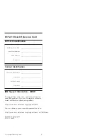
At command issuance (I-O registers setting contents)
1F7
H
(CM)
1
0
1
1
0
0
0
0
1F6
H
(DH)
×
×
×
DV
xx
1F5
H
(CH)
1F4
H
(CL)
1F3
H
(SN)
1F2
H
(SC)
1F1
H
(FR)
Key (C2h)
Key (4Fh)
xx
xx
Subcommand
Summary of Contents for MHC2032AT
Page 1: ...C141 E050 02EN MHC2032AT MHC2040AT MHD2032AT MHD2021AT DISK DRIVES PRODUCT MANUAL ...
Page 3: ......
Page 5: ......
Page 9: ......
Page 11: ......
Page 35: ......
Page 38: ...3 2 Mounting C141 E050 02EN 3 3 Figure 3 1 Dimensions MHD series 2 2 ...
Page 48: ...3 4 Jumper Settings C141 E050 02EN 3 13 Figure 3 14 Example 2 of Cable Select ...
Page 49: ......
Page 54: ...4 3 Circuit Configuration C141 E050 02EN 4 5 Figure 4 2 Circuit Configuration ...
Page 60: ...4 6 Read write Circuit C141 E050 02EN 4 11 Figure 4 4 Read write circuit block diagram ...
Page 71: ......
Page 164: ...5 6 Timing C141 E050 02EN 5 93 Figure 5 10 Data transfer timing ...
Page 203: ......
Page 207: ......
Page 209: ......
Page 216: ......
Page 219: ......