background image

45

U s e r - I n s t a l l a b l e   F e a t u r e s

Memory Upgrade
Module

Your LifeBook notebook has two memory slots, and the 
system comes with 256 MB, 512 MB, or 1 GB of factory-
installed memory. If you have a module installed in only 
one slot, you can increase your LifeBook notebook’s 
memory capacity by installing another memory upgrade 
module in the empty slot or by increasing the size of the 
single installed module. The minimum amount of 
memory in your system is 256 MB; the maximum 
amount is 2 GB (two 1 GB modules).

Your notebook supports dual-channel memory. Dual-
channel memory can have a significant effect upon your 
system’s performance. In order to support dual-channel 
memory, two DIMM modules must be installed in your 
computer.

Memory upgrades must be PC2-4200 DDR2-533 SO-
DIMM modules. To ensure 100% compatibility, we 
recommend that you only purchase additional memory 
from the Fujitsu on-line accessory store at:

us.fujitsu.com/computers

.

INSTALLING A MEMORY MODULE

1. Turn off power to your LifeBook notebook using the 

power/suspend/resume button, and remove any 
power adapter.

2. Make sure that all the connector covers are closed.

3. Turn the LifeBook notebook bottom side up, with 

the front panel toward you.

4. Remove the screws at the front of the memory 

upgrade module compartment. 

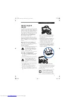
(Figure 4-11)


5. Remove the cover by tilting the front edge up and 

then pulling forward until the tabs on the cover are 
free.

Figure 4-11. Opening the Memory Upgrade Compartment

 6. Remove the memory upgrade module from the 

static guarded sleeve.

7. Align the memory upgrade module with the part 

side up. Align the connector edge of the memory 
upgrade module with the connector slot in the 
compartment. The connector will be pointing 
toward the rear of the LifeBook notebook. 

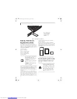
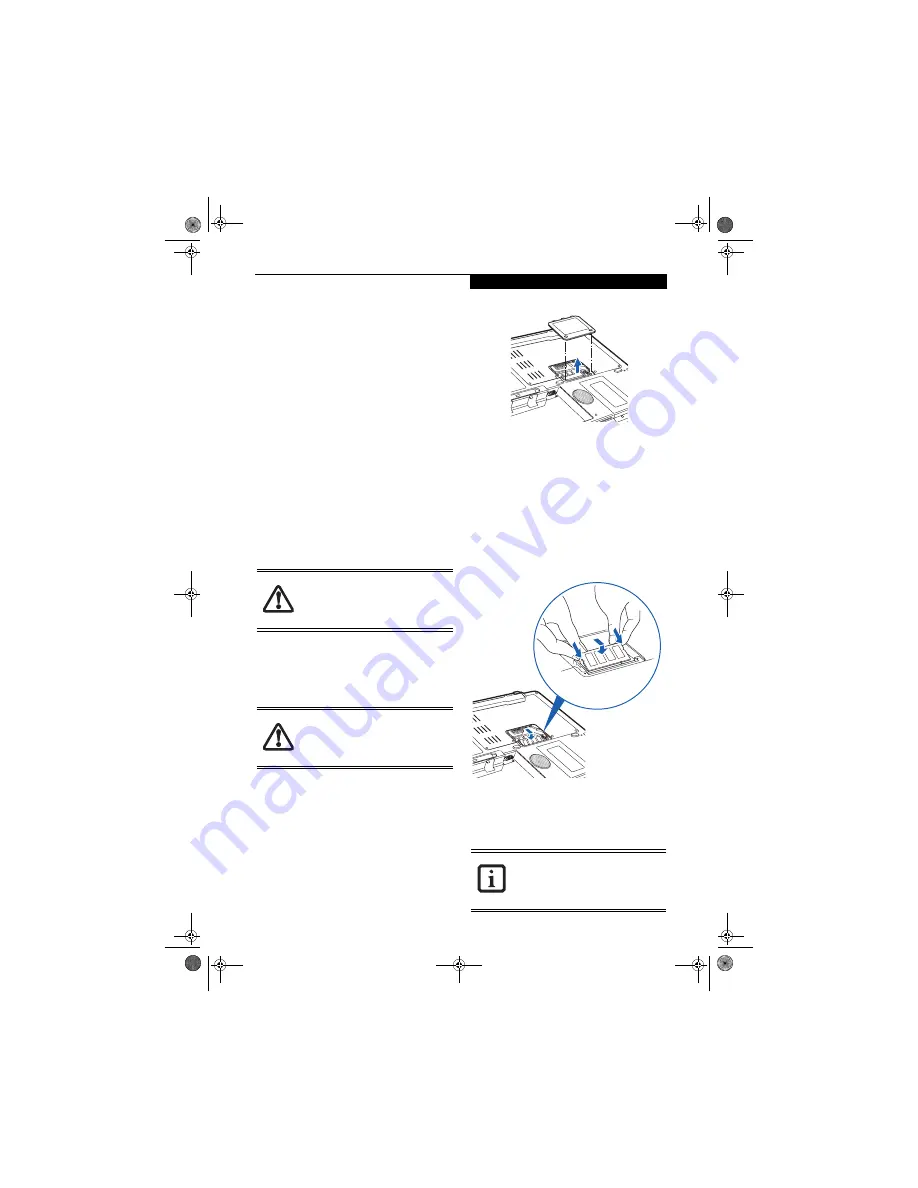
8. Insert the memory upgrade module at a 45° angle. 

Press the connector edge of the module firmly down 
and into the connector until it lodges under the 
retaining clip. You will hear a click when it is prop-
erly in place. 

(Figure 4-12)

Figure 4-12. Installing a Memory Upgrade Module

9. Replace the cover by hooking the tabs under the rear 

edge of the compartment opening and tilting down 
until flush with the bottom of your notebook.

10. Replace the screws.

Do not remove any screws from the 
memory upgrade module compartment, 
except the ones specifically shown in the 
directions for installing and removing the 
memory upgrade module.

The memory upgrade module can be 
severely damaged by electrostatic 
discharge (ESD). Be sure you are properly 
grounded when handling and installing the 
module.

The memory upgrade module is not 
something you should routinely remove 
from your notebook. Once it is installed, 
you should leave it in place unless you 
want to increase system memory capacity.

N6210.book  Page 45  Wednesday, May 18, 2005  10:24 AM

Summary of Contents for Lifebook N6210

Page 1: ... a registered trademark and or registered service mark of Intuit Inc or one of its subsidiaries in the United States and other countries InterVideo and WinDVD are registered trademarks of Inter video Inc Norton AntiVirus is a registered trademark of Symantec Corporation in the United States and other countries This product incorporates copyright protection technology that is protected by method cl...

Page 2: ...rt a gas leak in the vicinity of the leak Use only the power cord and batteries indicated in this manual Do not dispose of batteries in a fire They may explode Check with local codes for possible special disposal instructions To reduce the risk of fire use only No 26 AWG or larger UL Listed or CSA Certified Telecommunica tion Line Cord SAVE THESE INSTRUCTIONS For Authorized Repair Technicians Only...

Page 3: ...ows Keys 16 Cursor Keys 16 Function Keys 17 Volume Control Controlling the Volume 18 Touchpad Pointing Device Clicking 19 Double Clicking 19 Dragging 20 Scrolling 20 Touchpad Control Adjustment 20 3 GETTING STARTED WITH YOUR LIFEBOOK NOTEBOOK Power Sources Connecting the AC Adapter 23 Display Panel Opening the Display Panel 24 Adjusting Display Panel Brightness 24 Closing the Display Panel 24 Star...

Page 4: ...ling a Memory Module 45 Removing a Memory Upgrade Module 46 Checking the Memory Capacity 46 Device Ports Communications Ports 47 LAN Port 47 IEEE 1394 Jack 47 Universal Serial Bus USB 2 0 Ports 47 S Video Out Port 48 Microphone Jack 48 Headphone Jack 48 External Monitor Port 48 5 TROUBLESHOOTING Troubleshooting Identifying the Problem 51 Troubleshooting Table 52 Power On Self Test Messages 59 Mode...

Page 5: ...ary Glossary 93 IP address information About IP Addresses 95 Specifications Specifications 96 APPENDIX B TV TUNER USER S GUIDE TV Tuner Applications 99 Introducing the TV Tuner 99 TV Tuner Features 99 Remote Control Features 102 Connecting the TV tuner 103 Getting Started 105 Setting Up Skipping Channels 105 Starting closing Instant MyMedia 106 Watching TV Video without Booting Up 106 Copying from...

Page 6: ...L i f e B o o k N S e r i e s U s e r s G u i d e N6210 book Page 4 Wednesday May 18 2005 10 24 AM ...

Page 7: ...1 1 Preface N6210 book Page 1 Wednesday May 18 2005 10 24 AM ...

Page 8: ...2 L i f e B o o k N S e r i e s U s e r s G u i d e N6210 book Page 2 Wednesday May 18 2005 10 24 AM ...

Page 9: ...or your LifeBook notebook by clicking on the Fujitsu Web links LifeBook Accessories Web site URL link located in the Windows Start menu You can also reach Fujitsu Service and Support online by clicking on the Fujitsu Service and Support Web site URL link located in the Fujitsu Web links Service and Support Software folder of the Windows Start menu To ensure that you always have the most current dr...

Page 10: ...4 L i f e B o o k N S e r i e s U s e r s G u i d e N6210 book Page 4 Wednesday May 18 2005 10 24 AM ...

Page 11: ...5 2 Getting to Know Your LifeBook Notebook N6210 book Page 5 Wednesday May 18 2005 10 24 AM ...

Page 12: ...6 L i f e B o o k N S e r i e s U s e r s G u i d e N6210 book Page 6 Wednesday May 18 2005 10 24 AM ...

Page 13: ...feBook N6200 Series notebook computer Lithium ion battery pre installed AC adapter with AC power cord Figure 2 2 Phone Modem RJ 11 telephone cable Drivers and Applications Restore CD Restore DVD Getting Started Guide User s Guide this guide International Limited Warranty Brochure Microsoft associated materials Depending upon the configuration of your system one or more of the following items may a...

Page 14: ...l Button TV Button Wireless LAN Switch Media Player Buttons Power Suspend Resume Button Volume Level Volume Control DVD CD Button 9 10 11 12 13 14 15 16 Display Panel Latch Display Panel Keyboard Remote Control IR Port Status Indicator Panel Stereo Speakers Scrolling Button Touchpad Pointing Device Present on models with optional TV Tuner only N6210 book Page 8 Wednesday May 18 2005 10 24 AM ...

Page 15: ...stening to a DVD or CD or watching TV with the optional TV tuner See Control ling the Volume on page 18 for more information DVD CD Button The DVD TV button is present only on LifeBook models with an optional TV tuner See TV Tuner User s Guide on page 99 for more information Display Panel Latch The display panel latch locks and releases the display panel Display Panel The display panel is a color ...

Page 16: ...mini jack is present only on LifeBook models with an optional TV tuner See TV Tuner User s Guide on page 99 for more information S Video Input Port The S Video input port is present only on LifeBook models with an optional TV tuner See TV Tuner User s Guide on page 99 for more information Video Input Jack composite The video input jack composite is present only on Life Book models with an optional...

Page 17: ...ct Universal Serial Bus USB 2 0 or USB 1 1 devices See Universal Serial Bus USB 2 0 Ports on page 47 for more informa tion Optical Drive Eject Button The optical drive eject button is used to eject the media tray Optical Drive One of several different drives can be installed depending upon the configuration of your system See Optical Drive on page 35 for more information Figure 2 5 LifeBook notebo...

Page 18: ...on video signal to a compatible TV or VCR See S Video Out Port on page 48 for more information IEEE 1394 Port The IEEE 1394 port is used to connect Firewire devices such as digital cameras to your LifeBook notebook See IEEE 1394 Jack on page 47 for more information Figure 2 6 LifeBook notebook back panel 1 2 3 4 5 DC In Jack LAN Port Modem Port USB Ports S Video Out Port 6 7 8 9 USB Port IEEE 1394...

Page 19: ...for more information To protect your notebook from damage and to optimize system performance be sure to keep all air all vents unobstructed clean and clear of debris This may require periodic cleaning depending upon the environment in which the system is used Do not operate the notebook in areas where the air vents can be obstructed such as in tight enclosures or on soft surfaces like a bed or cus...

Page 20: ...ng overall performance Note The memory compartment cover also covers the location of the wireless LAN device the memory location is outlined with a dotted line in the illustration above See Memory Upgrade Module on page 45 for more information Air Flow Vents The air flow vents assist in proper cooling of the system Tilt Foot The tilt foot allows you to modify the angle of the keyboard to optimize ...

Page 21: ...e NumLock indicator shows that the internal keyboard is set in ten key numeric keypad mode CAPSLOCK INDICATOR The CapsLock indicator shows that your keyboard is set to type in all capital letters SCRLOCK INDICATOR The ScrLock indicator shows that your scroll lock is active 1 3 5 2 4 6 1 Power Indicator 2 Battery Charging Status Indicators 3 Hard Drive Optical Drive Access 4 NumLock Indicator 5 Cap...

Page 22: ...oard serves as a numeric keypad To activate the keypad functions press the NumLk button Using the keypad keys you can enter numerals 0 through 9 perform addition subtraction multiplication or division and enter decimal points using the keys designated as ten key function keys When NumLk is not active you can use the numeric keypad to navigate Home End Page Up Page Down left right up down The keys ...

Page 23: ...5 Pressing F5 while holding Fn allows you to toggle between video compensation and no compensation Video compensation controls spacing on the display When it is enabled displays with less than 1024 x 768 or 800 x 600 pixel resolution will still cover the entire screen Fn F6 Pressing F6 repeatedly while holding Fn will lower the brightness of your display Fn F7 Pressing F7 repeatedly while holding ...

Page 24: ...ume of your notebook Pressing F9 repeatedly while holding Fn will increase the volume of your notebook Volume can be controlled by many volume controls that are set within individual applications Certain external audio devices you might connect to your system may have hardware volume controls Each source discussed above puts an upper limit on the volume level that must then be followed by the othe...

Page 25: ...ursor to the item you wish to select press the right button once and then immediately release it You also have the option to perform the clicking operation by tapping lightly on the Touchpad once Figure 2 12 Figure 2 12 Clicking DOUBLE CLICKING Double clicking means pushing and releasing the left button twice in rapid succession This procedure does not function with the right button To double clic...

Page 26: ...d after the final tap Next move the object to its new location by moving your finger across the Touchpad and then release your finger Figure 2 14 Figure 2 14 Dragging SCROLLING Using the scroll buttons allows you to scroll up and down a page easily without using the window scroll bars To move up a page press the upper part of the button To move down a page use the lower part of the button Figure 2...

Page 27: ...21 3 Getting Started N6210 book Page 21 Wednesday May 18 2005 10 24 AM ...

Page 28: ...22 L i f e B o o k N S e r i e s U s e r s G u i d e N6210 book Page 22 Wednesday May 18 2005 10 24 AM ...

Page 29: ...utlet Figure 3 1 Switching from AC Adapter Power to Battery Power 1 Be sure that you have a charged battery installed 2 Unplug the AC adapter Figure 3 1 Connecting the AC Adapter 1 2 DC Power Jack DC Output Cable 3 4 AC Adapter AC Cable 1 2 3 4 When you run the N6200 Series Life Book on battery power by default the CPU will slow down approximately by half in order to optimize battery life This fea...

Page 30: ...Keyboard to Change Display Brightness Fn F6 Pressing this key combination repeatedly will lower the brightness of your display Fn F7 Pressing this key combination repeatedly will increase the brightness of the display CLOSING THE DISPLAY PANEL 1 Holding the edge of your display panel pull it forward until it is flush with the body of your LifeBook notebook 2 Push down until you hear a click This w...

Page 31: ... is performing a standard boot sequence including a Power On Self Test POST When the boot sequence is completed without a failure and without a request for the BIOS Setup Utility the system displays the operating system s opening screen The boot sequence is executed when You turn on the power to your LifeBook notebook You restart your LifeBook notebook from the Win dows Shut Down dialog box The so...

Page 32: ...Information on page 3 for more information If you would simply like to move on and register at a later time you may click the Skip button and you will go directly to the Condition of Use page Registration If your connection is successful you will go to a Regis tration Confirmation page On this page enter the requested information then check the box at the bottom to register your copy of Windows wi...

Page 33: ... bottom right of the screen These icons provide links to utilities that you will frequently access The icon is automatically deleted after you launch Click Me and restart the system FUJITSU DRIVER UPDATE UTILITY Your system has a convenient tool called the Fujitsu Driver Update FDU utility With FDU you can choose to automatically or manually go to the Fujitsu site to check for new updates for your...

Page 34: ...nts except those necessary to maintain system memory and allow for restarting Your LifeBook notebook can be put in Suspend mode by Pressing the Power Suspend Resume button when your system is turned on Selecting Standby from the Windows Shut Down menu Timing out from lack of activity Allowing the battery to reach the Dead Battery Warning condition Your LifeBook notebook s system memory typically s...

Page 35: ...ed in Windows RESTARTING THE SYSTEM If your system is on and you need to restart it be sure that you use the following procedure 1 Click the Start button and then click Turn Off Computer 2 Select the Restart option from within the Windows Shut Down dialog box 3 Click OK to restart your LifeBook notebook Your notebook will shut down and then reboot POWER OFF Before turning off the power by choosing...

Page 36: ...30 L i f e B o o k N S e r i e s U s e r s G u i d e N6210 book Page 30 Wednesday May 18 2005 10 24 AM ...

Page 37: ...31 4 User Installable Features N6210 book Page 31 Wednesday May 18 2005 10 24 AM ...

Page 38: ...32 L i f e B o o k N S e r i e s U s e r s G u i d e N6210 book Page 32 Wednesday May 18 2005 10 24 AM ...

Page 39: ...utdown procedure Low Battery State When the battery is running low a low battery notifica tion message will appear If you do not respond to the low battery message the batteries will continue to discharge until they are too low to operate When this happens your LifeBook notebook will go into Suspend mode There is no guarantee that your data will not be lost once the notebook reaches this point Not...

Page 40: ...ies The Status Indicator panel displays the battery status via the Battery Status indicator to show the charge level available in that battery If the display is flashing red it means that the battery is damaged and must be replaced so it does not damage any other parts of your LifeBook notebook REPLACING THE BATTERY With the purchase of an additional battery you can have a fully charged spare to s...

Page 41: ...ar a click Figure 4 4 REMOVING MEDIA 1 Push and release the eject button on the front of the optical drive This will stop the drive and the holder tray will come out of the notebook a short distance 2 Gently pull the tray out until the disc can easily be removed from the tray 3 Carefully remove the media disc from the holder tray 4 Gently push the holder tray back in until you hear a click Figure ...

Page 42: ... you have the option of altering how the movie should play and what you wish to view You can do this by using the DVD CD RW Combo Drive control panel and the mouse To open a dropdown menu for options right click on the movie screen Using the Optical Drive Control Panel The WinDVD optical drive software allows you to watch the movie much like a VCR player You have the option to pause rewind fast fo...

Page 43: ...uous Play and Disable Stop Eject Button CD Removal If you click on Always on top the desktop controls will always be seen on your screen no matter what other application you are running If you click on Continuous Play your media player will automatically start over at the beginning of the disc in the drive as soon as it finishes the last track If you click on Disable Stop Eject Button CD Removal t...

Page 44: ...tebook can support on a single battery If you are watching a DVD movie on battery power you may need to swap in an additional charged battery or attach AC power during the movie to view it in its entirety To Watch a Movie on Battery Power 1 Have an additional fully charged battery or your AC adapter ready for use 2 Start watching your DVD movie 3 When the low battery warning occurs immediately sto...

Page 45: ...UNCTION The Auto Insert Notification function allows your Life Book notebook to automatically start a DVD CD as soon as it is inserted in the optical drive and the tray is closed Your notebook will begin playing an audio DVD CD or will start an application if the DVD CD includes an auto run file To prevent a CD from playing automatically as soon as it is inserted refer to the related help file for...

Page 46: ...itecture xD Cards work the same as Memory Sticks and SD Cards but they are much smaller than either one Using an xD Card in the slot requires an adapter xD Cards are primarily used to store and transfer images with devices such as cell phones Figure 4 8 Memory Stick Secure Digital and xD Cards INSTALLING MEMORY STICK SD XD CARDS Memory Sticks SD Cards and xD Cards are installed in the Memory Stick...

Page 47: ...nd from the slot approximately half an inch when installed REMOVING A MEMORY STICK SD XD CARD To remove a Memory Stick SD Card or xD Card follow these easy steps Push the Memory Stick SD Card or xD Card adapter in until it unlatches It will then eject from the slot for removal When installing a Memory Stick SD or xD card in the slot be sure the card label is facing downward When installed a Memory...

Page 48: ...mentation for the correct procedure Before you reformat your hard disk drive please note Any data that currently resides on your hard disk drive must be backed up to floppy disks or other data storage media or it will be permanently lost These back up disks can then be used to reinstall and restore your data See your operating system manual for more information on backing up your data files All ap...

Page 49: ...r card Some cards may require your note book to be in Suspend Mode or Off during removal 2 Unlock the card from the slot by pressing the eject button When pressed the button will pop out 1 1 ExpressCard Slot 2 PC Card Eject Button 2 3 4 3 PC Card Slot 4 PC Card When you receive your system there may be dummy cards installed in the card slots Before installing a PC Card or ExpressCard remove the du...

Page 50: ...into the slot This will cause the card to be ejected slightly out of the slot allowing you to remove the card If the PC Card has an external connector and cable do not pull the cable when removing the card Installing or removing an ExpressCard during your notebook s shutdown or bootup process may damage the card and or your notebook Do not insert an ExpressCard into a slot if there is water or any...

Page 51: ...Figure 4 11 5 Remove the cover by tilting the front edge up and then pulling forward until the tabs on the cover are free Figure 4 11 Opening the Memory Upgrade Compartment 6 Remove the memory upgrade module from the static guarded sleeve 7 Align the memory upgrade module with the part side up Align the connector edge of the memory upgrade module with the connector slot in the compartment The conn...

Page 52: ...stem memory capacity by either adding or removing a memory upgrade module be sure to check that your notebook has recognized the change You can check the memory capacity by clicking Start Control Panel then double clicking the System icon Select the General tab and check the amount of memory under Computer After installing your added memory module you must complete the Resetting the Save to Disk P...

Page 53: ...onnect a 1394 device follow these steps Figure 4 16 Figure 4 16 IEEE 1394 Interface UNIVERSAL SERIAL BUS USB 2 0 PORTS The four Universal Serial Bus USB 2 0 ports allow you to connect USB devices such as game pads pointing devices keyboards and speakers There is one USB 2 0 port on the right side and three on the rear panel Figure 4 17 USB 2 0 is downward compatible with USB 1 1 devices so older U...

Page 54: ...llow these easy steps 1 Align the connector with the port opening 2 Push the connector into the port until it is seated 3 Tighten the two hold down screws located on each end of the connector Figure 4 19 External Monitor Connection There are several types of cables for connecting a digital electronic device e g MD player to the digital audio out connector depending on the connector type The connec...

Page 55: ...49 5 Troubleshooting N6210 book Page 49 Wednesday May 18 2005 10 24 AM ...

Page 56: ...50 L i f e B o o k N S e r i e s U s e r s G u i d e N6210 book Page 50 Wednesday May 18 2005 10 24 AM ...

Page 57: ...f at least 10 seconds before you turn it on 6 Go through the boot sequence 7 If the problem has not been resolved refer to the Troubleshooting Table that follows for more detailed troubleshooting information 8 If you have tried the solutions suggested in the Trou bleshooting Table without success contact your support representative n Toll free 1 800 8Fujitsu 1 800 838 5487 E mail 8fujitsu us fujit...

Page 58: ...ones BIOS audio settings are incorrect Set the BIOS setup utility to the default values within the Multimedia Device Configuration menu See BIOS Setup Utility on page 25 for more information Software driver is not config ured correctly Refer to your application and operating system documentation for help DVD CD ROM Drive Problems Notebook fails to recognize DVD CDs DVD CD is not pushed down onto c...

Page 59: ...set so your oper ating system cannot be started without a password Verify your password and security settings The hard disk drive has crashed Contact Fujitsu or your local authorized reseller for a replacement hard disk drive Keyboard or Mouse Problems The built in keyboard does not seem to work Your application has locked out your keyboard Try to use your integrated pointing device to restart you...

Page 60: ... address selected for your device See your device documentation and software docu mentation to determine the required I O address Change the settings in the BIOS setup utility See BIOS Setup Utility on page 25 for more information Your device and another device are assigned the same I O address Check all I O addresses located within the BIOS setup utility and any other installed hardware or softwa...

Page 61: ...ers are set for auto timeouts which are too short for your operating needs Press any button or key on the keyboard or move the mouse If that fails push the Power Suspend Resume button Check your power management settings or close your applications and go to the Power Savings menu of the setup utility to adjust the timeout values to better suit your operation needs You are operating on battery powe...

Page 62: ...y be a conflict with the application software Close all applications and try the button again The system powers up and displays power on informa tion but fails to load the operating system The boot sequence settings of the setup utility are not compatible with your configuration Set the operating source by pressing the ESC key while the Fujitsu logo is on screen or use the F2 key and enter the set...

Page 63: ...button The display may be shut off by Standby mode Auto Suspend or Video Timeout The notebook turned on with a series of beeps and your display is blank Power On Self Test POST has detected a failure which does not allow the display to operate Contact your support representative Your system display won t turn on when the system is turned on or when the system has resumed The system may be password...

Page 64: ...u can fill the screen but have less resolution by changing your display compres sion setting See Video Features submenu located within the Advanced menu of the BIOS See BIOS Setup Utility on page 25 for more information You have connected an external monitor and it does not display any information Your BIOS setup is not set to enable your external monitor Toggle the video destination by pressing F...

Page 65: ...the system there may be a serious fault which might cause you to lose data if you continue Contact your support representative Incorrect Drive A type run SETUP Type of floppy drive A not correctly identified in Setup This means that the floppy disk drive type identified in your setup utility does not agree with the type detected by the Power On Self Test Run the setup utility to correct the incons...

Page 66: ...ed life of 2 to 3 years System BIOS shadowed System BIOS copied to shadow RAM System CMOS checksum bad run SETUP BIOS CMOS RAM has been corrupted or modified incorrectly perhaps by an application program that changes data stored in BIOS memory Run Setup and reconfigure the system System RAM Failed at offset nnnn System memory failed at offset nnnn of in the 64k block at which the error was detecte...

Page 67: ...fy that your system is set up to boot from the DVD drive To verify change the boot up priority rather than booting up from the hard drive or an external floppy disk drive perform the following steps 1 Start your system and press the F2 key when the Fujitsu logo appears You will enter the BIOS Setup Utility 2 Using the arrow keys go to the Boot menu 3 Arrow down to the Boot Device Priority submenu ...

Page 68: ...Driver Update FDU utility With FDU you can choose to automatically or manually go to the Fujitsu site to check for new updates for your system The FDU icon should appear in the system tray at the bottom right of your screen roll the cursor over the icons to find the correct one If the FDU icon does not appear in the system tray it can be started by going to Start All Programs and clicking on Fujit...

Page 69: ...63 6 Care and Maintenance N6210 book Page 63 Wednesday May 18 2005 10 24 AM ...

Page 70: ...64 L i f e B o o k N S e r i e s U s e r s G u i d e N6210 book Page 64 Wednesday May 18 2005 10 24 AM ...

Page 71: ... or sharp objects on the computer If you are carrying your LifeBook notebook in a brief case or any other carrying case make sure that there are no objects in the case pressing on the lid Do not drop your LifeBook notebook Do not touch the screen with any sharp objects Cleaning your LifeBook notebook Always disconnect the power plug Pull the plug not the cord Clean your LifeBook notebook with a da...

Page 72: ...cil or an eraser on a disk or disk label Avoid storing the floppy disks in extremely hot or cold locations or in locations subject to severe temperature changes Store at temperatures between 50º F 10ºC and 125ºF 52ºC Do not touch the exposed part of the disk behind the metal shutter Caring for your Floppy Disk Drive To clean wipe the floppy disk drive clean with a dry soft cloth or with a soft clo...

Page 73: ... with the power on Avoid using or storing the drive where it will be exposed to extreme temperatures Avoid using or storing the drive where it is damp or dusty Avoid using or storing the drive near magnets or devices that generate strong magnetic fields Avoid using or storing the drive where it will be subjected to shock or vibration Do not disassemble or dismantle the media drive PC CARDS Caring ...

Page 74: ...68 L i f e B o o k N S e r i e s U s e r s G u i d e N6210 book Page 68 Wednesday May 18 2005 10 24 AM ...

Page 75: ...69 7 Specifications N6210 book Page 69 Wednesday May 18 2005 10 24 AM ...

Page 76: ...70 L i f e B o o k N S e r i e s U s e r s G u i d e N6210 book Page 70 Wednesday May 18 2005 10 24 AM ...

Page 77: ...tor Card Integrated ATI Mobility RADEON X600 with 128 MB of dedicated video memory AUDIO The Intel 915PM controller supports Intel High Defini tion HD Audio HD Audio delivers the features and high end performance of an add in audio card and is capable of playing back more channels of higher quality than was previously possible Intel 82801FBM ALC260 Stereo headphone jack 1 Vrms or less minimum impe...

Page 78: ...on key Fn Windows keys 2 Start key and application key Key pitch 19 mm Key stroke 3 0 mm Dedicated ten key numeric keypad Built in Alps Wide Touchpad pointing device with left and right buttons and scrolling button External Keyboard Support USB compatible External Mouse Support USB compatible Management Standard DMI 2 0 ready WFM 2 0 compliant POWER Batteries Main 8 cell Lithium ion battery rechar...

Page 79: ...er viruses It assists in the protection of the data currently residing on your hard disk from destruction or contamination The 90 day trial version is activated upon your acceptance of soft ware license agreement After 90 days it will be neces sary to purchase a subscription from Symantec to download latest virus definitions See your online help or manual for more information on how and when to ru...

Page 80: ...74 L i f e B o o k N S e r i e s U s e r s G u i d e N6210 book Page 74 Wednesday May 18 2005 10 24 AM ...

Page 81: ...75 8 Glossary N6210 book Page 75 Wednesday May 18 2005 10 24 AM ...

Page 82: ...76 L i f e B o o k N S e r i e s U s e r s G u i d e N6210 book Page 76 Wednesday May 18 2005 10 24 AM ...

Page 83: ... PCI architecture Command An instruction which you give your operating system Example run a particular application or format a floppy disk Configuration The combination of hardware and software that makes up your system and how it is allocated for use CRT Cathode Ray Tube A display device which uses a beam of electronic particles striking a luminescent screen It produces a visual image by varying ...

Page 84: ...spinning platter of magnetic data storage media where the platter is very stiff Hexadecimal A decimal notation for the value of a 4 bit binary number 0 9 A B C D E F Example 2F in hexa decimal 00101111 in binary 47 in decimal I O Input Output Data entering and leaving your LifeBook notebook in electronic form I O Port The connector and associated control circuits for data entering and leaving your...

Page 85: ... performs a specific function associated with but not integral to a computer Examples a printer a modem a CD ROM Pitch keyboard The distance between the centers of the letter keys of a keyboard Pixel The smallest element of a display a dot of color on your display screen The more pixels per area the clearer your image will appear POST Power On Self Test A program which is part of the BIOS which ch...

Page 86: ... pressed from resting to fully depressed Suspend To make inoperative for a period of time Your LifeBook notebook uses various suspension states to reduce power consumption and prolong the charge of your battery SVGA Super VGA S Video Super Video A component video system for driving a TV or computer monitor System Clock An oscillator of fixed precise frequency which synchro nizes the operation of t...

Page 87: ...ermine the number of devices that may be connected to a telephone line Exces sive RENs on a telephone may result in the devices not ringing in response to an incoming call In most but not all areas the sum of RENs should not exceed five 5 0 To be certain of the number of devices that may be connected to a line as determined by the total RENs contact the local telephone company For products approve...

Page 88: ...d Industrie Canada applicables au matériel terminal Cette confor mité est confirmée par le numéro d enregistrement Le sigle IC placé devant le numéro d enregistrement signifie que l enregistrement s est effectué conformé ment à une déclaration de conformité et indique que les spécifications techniques d Industrie Canada ont été respectées Il n implique pas qu Industrie Canada a approuvé le matérie...

Page 89: ...83 Appendix A Integrated Wireless LAN User s Guide Optional Device N6210 book Page 83 Wednesday May 18 2005 10 24 AM ...

Page 90: ...84 L i f e B o o k N S e r i e s U s e r s G u i d e N6210 book Page 84 Wednesday May 18 2005 10 24 AM ...

Page 91: ...ese limits are designed to provide reasonable protection against harmful interference in a residential installa tion This equipment generates uses and can radiate radio frequency energy If not installed and used in accordance with the instructions it may cause harmful interference to radio communications However there is no guarantee that interfer ence will not occur in a particular installation I...

Page 92: ...ters However that range will increase or decrease depending on factors such as number of walls reflective material or inter ference from external RF sources The WLAN device supports the following encryption methods WEP TKIP CKIP and AES encryption WIRELESS LAN MODES USING THIS DEVICE Ad Hoc Mode See Figure A 1 Ad Hoc Mode refers to a wireless network where wireless network connectivity between mul...

Page 93: ...ration of the WLAN device DEACTIVATING THE WLAN DEVICE Deactivation using the Wireless On Off Switch The WLAN device can be deactivated quickly and effi ciently by toggling the Wireless On Off Switch to the Off position Figure A 3 The wireless On Off switch has no effect on non Wireless LAN models Deactivation using Intel PROSet for Wireless Utility The WLAN device can be deactivated in Windows us...

Page 94: ...icon Intel PROSet Wireless to execute the Intel PROSet for Wireless utility 4 Click the Add button The General Settings dialog displays 5 Enter a profile name in the Profile Name field 6 Enter the network SSID in the Network Name SSID field 7 Click Infrastructure or Ad Hoc for the operating mode 8 Click Advanced 9 The Mandatory Access Point option is only used if Infrastructure mode is selected Us...

Page 95: ...hen enter data for IP address and Subnet mask See page 95 for IP address setting For access point infrastructure connection If your network uses DHCP select Obtain an IP address automatically and Obtain DNS server address automatically If your network uses static IP addresses consult with your network adminis trator for the correct IP address settings 8 Click the OK button Processing will return t...

Page 96: ...yed 9 Click File and Printer Sharing for Microsoft Net works and then click the OK button Processing will return to the Wireless Network Connection Properties window and File and Printer Sharing for Microsoft Networks will be added to the list 10 Click the Close button Setting the file sharing function The procedure for setting the file sharing function follows with the work folder in drive C as a...

Page 97: ...status of the radio When the radio is turned off or the com puter is not yet connected some of the conditions will not be displayed Profile Name The current configuration profile is displayed Network Name SSID Displays the Network Name SSID currently used by the radio IP Address The IP address of the current profile Signal Quality Displays a message stating the current quality of the signal Signal...

Page 98: ...or removing any obstacles for better sight The WLAN device has been deactivated or disabled Check if the wireless switch is turned ON Also verify Disable Radio is not checked in Network setting window The computer to be connected is turned off Check if the computer to be connected is turned ON RF interference from Access Points or other wireless networks The use of identical or overlapping RF chan...

Page 99: ... address or IEEE MAC address is the 48 bit address typically written as twelve hexadecimal digits 0 through 9 and A through F or as six hexadecimal numbers separated by periods or colons e g 0080002012ef 0 80 0 2 20 ef which uniquely identifies a computer that has an Ethernet interface MTU Maximum Transmission Unit The maximum size of data which can be transmitted at one time in networks including...

Page 100: ...her so all access points and all devices attempting to connect to a specific WLAN must use the same SSID A device will not be permitted to join the BSS unless it can provide the unique SSID Because the SSID is broadcast in plain text it does not supply any security to the network Subnet mask TCP IP network is controlled by being divided into multiple smaller networks subnets IP address consists of...

Page 101: ...ressed with four values in the range between 1 and 255 Set the each computer as follows The value in paren theses is a subnet mask Example Computer A 192 168 100 2 255 255 255 0 Computer B 192 168 100 3 255 255 255 0 Computer C 192 168 100 4 255 255 255 0 Computer X 192 168 100 254 255 255 255 0 IP addressing is much more complicated than can be briefly explained in this document You are advised t...

Page 102: ...ification Type of network The Intel PRO Wireless 2915ABG Network Connections WLAN device conforms to IEEE 802 11a and 802 11b g Wi Fi based Transfer rate Automatic switching IEEE 802 11a g 54 Mbps maximum data rate IEEE 802 11b 11 Mbps maximum data rate Active frequency 802 11b g 2400 2473 MHz 802 11a 4900 5850 MHz Number of channels 802 11a 8 independent channels 802 11b g 11 channels 3 non overl...

Page 103: ...97 Appendix B TV Tuner User s Guide Optional Device N6210 book Page 97 Wednesday May 18 2005 10 24 AM ...

Page 104: ...98 L i f e B o o k N S e r i e s U s e r s G u i d e N6210 book Page 98 Wednesday May 18 2005 10 24 AM ...

Page 105: ...cated in the Fujitsu LifeBook Media Player Panel above the keyboard The features of the Fujitsu LifeBook that are related to the TV Tuner including Media Player Panel are itemized in the table below This manual deals primarily with using Instant MyMedia with the TV Tuner For detailed information about the WinDVD and WinDVR applications please see the associated Help files by opening the applicatio...

Page 106: ...n while a DVD or video is playing play will stop temporarily 6 Back When you press this button while an audio CD or a DVD is being played in DVD CD mode the player will return to the previous track if the current track hasn t yet started If the track has already started you will return to the beginning of the current track 7 Next When you press this button while an audio CD or a DVD is being playe...

Page 107: ...age input from a device connected to this jack is displayed when Composite input is selected 4 S Video Input Port Used to connect to the S video output port of external video devices The image input from a device connected to this jack is displayed when S Video input is selected 5 Antenna Mini Jack Used to connect a TV or cable TV antenna using the RF adapter cable included with the kit 1 2 3 4 5 ...

Page 108: ...o be arrayed on the screen 7 Cursor Move The cursor move buttons allow you to move the cursor Up Down Left or Right 8 Record Pressing the Record button while you are in MyMedia TV mode will start the recording on DVD RAM or hard drive Pressing this button while in WinDVR post boot allows you to record to the notebook s hard drive or any of the applicable disc media 9 Play Pause If you press this b...

Page 109: ... the notebook is in TV or Video mode when the button is pressed it will be switched into DVD CD mode 20 TV When this button is pressed power to the notebook is deactivated Instant MyMedia is activated and the notebook is automatically switched to TV mode 21 List When using Instant MyMedia press the List button to display a list of video files on the hard disk drive 22 Menu When using Instant MyMed...

Page 110: ...book by matching the colors of the cable with the colors of the jacks See Figure B 8 Figure B 8 Audio Input Connection Connecting an External Video Device You can view videos and images from an external device on your notebook Depending upon the configuration of the device you will need to purchase either a composite RCA video cable Figure B 9 or an S Video 4 pin cable Figure B 11 You will also ne...

Page 111: ...Select Antenna or Cable depending upon how your tuner is connected Press Enter 5 In the left hand panel select Favorite Channel List To automatically assign a broadcast station to unas signed channels set the selection to On 6 Select Auto Scan with the cursor buttons select Run then press Enter 7 A channel search will begin During the channel search channels are switched one after another this cou...

Page 112: ...out activating the notebook s operating system also called booting up the notebook Watching Television Switching to TV Mode 1 Display the main menu of Instant MyMedia Starting Instant MyMedia on page 106 2 Select TV using the cursor buttons on the remote control then press the Enter button 3 If the TV is not selected press the TV Video but ton on the remote control to switch to TV mode Each time t...

Page 113: ...COPYING FROM AN EXTERNAL DEVICE TO DVD To copy video from an external device such as a VCR or DVD player perform the following steps 1 Connect the external device in accordance with Connecting the TV tuner on page 103 2 Start Instant MyMedia by pressing the TV button on the remote control 3 Insert a blank DVD RAM disc in the notebook media player 4 Press the TV Video button on the remote control a...

Page 114: ...sc 2 Press the MyMedia button 3 Using the cursor control buttons select Settings 4 Select Quick format or Full format and press the Enter button Formatting will start You are advised to run the system using the AC adapter when recording programs on a DVD in order to preserve battery power Recording can be done with either Instant MyMedia pre boot or WinDVR post boot The following table reflects th...

Page 115: ...ess the MyMedia button on the remote control to display the main menu 2 Select Playback from the menu and press the Enter button 3 Select the folder in which TV programs or videos to be played are stored and press the Enter button 4 Select the TV program or video you want to play and press the Enter button Three options are dis played Play Delete and Cancel If Play is selected the TV programs or v...

Page 116: ...button is pressed the speed cycles through four stages When you press the Play Pause button normal play speed is resumed Fast Forward and rewind speeds are double speed x 4 speed x 8 speed x 20 speed Track skip When you press the Next button during the play the track being played is skipped and the head of the next track is started to play If you press the Back button immediately after a track is ...

Page 117: ...n you press the Stop Eject button during the play play is temporarily stopped Pressing Stop Eject again causes the tray to eject slightly from the optical drive to eject the disc The Stop Eject button on the notebook can be used instead of the Stop Eject button on the remote control Changing angles Pressing the Angle button if multiple angles are set to a DVD the next angle switched is displayed I...

Page 118: ... press the Enter button Only the DVDs having the region code newly set can be played Setting the play start position Set the position for starting the play of DVDs 1 Press the Menu button to display the menu and select Auto Resume from the list 2 In the right column select the setting you would like and press the Enter button Start from the beginning Play from the start of the disc regardless of t...

Page 119: ...ot be changed during the play of DVDs Press the Stop Eject button to operate DVD Movie Standards G General Audiences All Ages Admitted Contains nothing which would in the view of the rating board be offensive to parents whose younger children view the film PG Parental Guidance Suggested Some Material May Not Be Suitable For Children This is a film which clearly needs to be examined by parents befo...

Page 120: ...ton select Settings then press the Enter button Select the Parental Control tab and press the Enter button 2 If you have already set a password go to Password Change and enter the password in Input Password Press the Enter button 3 If you have not yet set a password select Password change and select New password and press the Enter button 4 Input a password with the 1 9 buttons and press the Enter...

Page 121: ...ncel the off timer select Disable 3 When the time specified has elapsed Instant MyMedia is automatically terminated powering off the notebook Adjusting the display quality The brightness and colors of the picture can be adjusted as you like Each video adjustment is applied to all TV DVD CD and video play modes The setting cannot be changed by each mode 1 Press the Menu button to display the menu a...

Page 122: ...ing Channels on page 105 TV broadcast pictures are not clear The antenna cable is not connected properly Connect the antenna cable correctly Connecting an Anten na on page 103 The TV image appears as double or triple images Objects in the environment e g buildings or mountains could have an influence on broadcast quality Adjust the position and direction of the antenna Stripes and dots appear duri...

Page 123: ...ad The notebook is in Standby mode Power down the notebook Refer to your notebook s user guide The BIOS setting for Instant My Media is disabled Change the BIOS setting of Instant MyMedia Refer to your notebook s user guide Only certain remote control buttons respond TV broadcasts are being recorded During recording most buttons are disabled with the exceptions of volume and pause Recording can t ...

Page 124: ...store is in process is displayed and your notebook will start copying files 8 When restore is complete a message appears prompting you to remove the Restore disc Remove the disc and press the Y key The system will reboot If the recovery menu is not displayed eject the disc to check that a proper disc is installed After checking press the Delete key while pressing the Ctrl key and the Alt key to re...

Page 125: ...udio Output Stereo US voice multiplex output support Interface Headphones 3 5mm stereo mini jack output 1 mW or more load impedance 32 Ohm Antenna Input Mini jack RF adapter cable included 75 ohm Video Input S Video 4 pins x 1 and Composite Video x 1 NTSC 525line 60 Hz Audio Input Left white Right red RCA type x 1 each max 1 Vrms Encoder Video compression method MPEG2 Bit rate 2 4 6 8 Mbps selecta...

Page 126: ...tative at 1 800 8FUJITSU 1 800 838 5487 E mail 8fujitsu us fujitsu com Web Site http www computers us fujitsu com sup port Remote Control Feature Specifications Communications Scheme Infrared rays Effective Distance location see figure below Battery AA dry battery x 2 Battery Life Approximately 6 months when using dry manganese batteries 30 o 3 m 30 o 30 o 3 m IR Receiver N6210 book Page 120 Wedne...

Page 127: ...121 Index N6210 book Page 121 Wednesday May 18 2005 10 24 AM ...

Page 128: ...122 L i f e B o o k N S e r i e s U s e r s G u i d e N6210 book Page 122 Wednesday May 18 2005 10 24 AM ...

Page 129: ...77 CapsLock Indicator 15 Clicking 19 Color Resolution 71 Communications Port 47 copyright and trademark information 1 Cursor 19 Cursor Keys 16 D DC In Jack 12 23 101 DC Output Cable 23 Desktop Control Panel 37 Device Ports 47 72 Disk care 66 Display 57 Display Panel 9 57 adjusting 24 brightness 24 closing 24 latch 9 opening 24 Display quality 113 Display Timeout 29 Display types 115 Dolby Headphon...

Page 130: ...care 65 storing 65 traveling 65 M Memory 71 capacity 46 compartment 14 45 installing 45 removing 46 upgrade module 45 Memory Stick SD Card 40 installing 40 removing 41 Memory Stick SD Card Slot 11 Memory Upgrade Module 54 Microphone Jack 48 Modem Jack 13 47 Modem Result Codes 60 N Numeric Keypad 16 NumLk Indicator 15 O Optical Drive 11 35 71 101 Control Panel 36 loading 35 removing media 35 tray r...

Page 131: ...pend 80 Suspend Mode 28 S Video Out Port 12 System Memory 71 T Theft Prevention Lock Slot 71 TouchPad 19 buttons 19 controls 20 Touchpad 9 Touchpad Pointing Device 9 Troubleshooting 51 116 Audio does not come on or sound right 116 Certain procedures don t work properly 117 Recording can t be performed 117 The screen does not appear 116 The screen image is distorted 116 TV button 100 TV Tuner Adjus...

Page 132: ... 109 Setting the Timer 115 Stop Eject 111 S Video Cable Connection 105 S Video Input Port 101 Switching to TV Mode 106 Timer 115 Transfer of Chapter 111 Usable Disc Formats 108 Using bookmarks 113 Using the DVD menu 112 Video Input Jack Composite 101 Volume Control button 100 Watching Recorded TV Programs or Videos 109 Watching Television 106 Watching TV Video without Booting Up 106 Watching Video...

Page 133: ...N6210 book Page 127 Wednesday May 18 2005 10 24 AM ...

Page 134: ...N6210 book Page 128 Wednesday May 18 2005 10 24 AM ...

Page 135: ...N6210 book Page 129 Wednesday May 18 2005 10 24 AM ...

Page 136: ...N6210 book Page 130 Wednesday May 18 2005 10 24 AM ...

Reviews: