background image

48

L i f e B o o k C S e r i e s – S e c t i o n F o u r

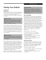
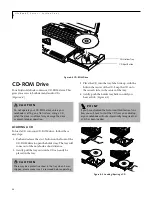
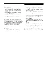
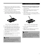
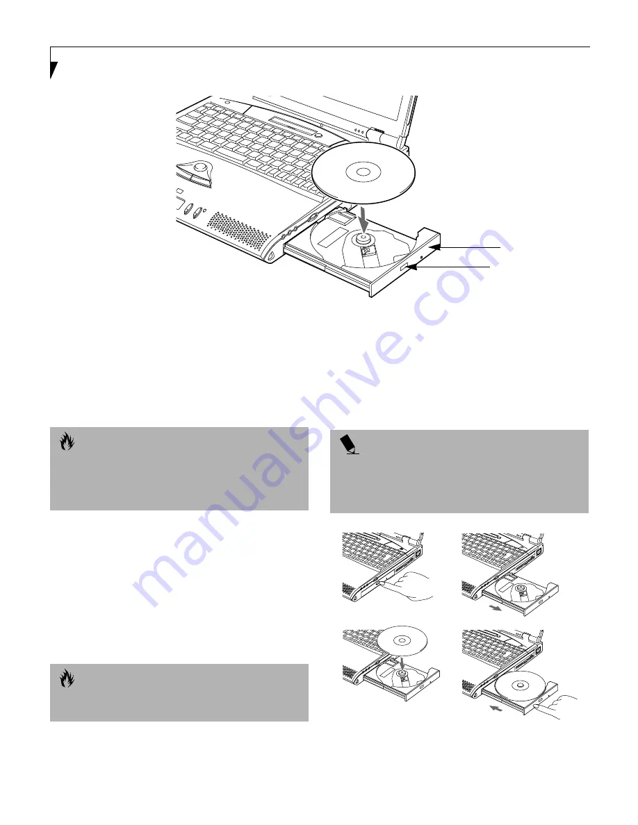
Figure 4-4 CD-ROM Drive

CD-ROM Drive

Your Fujitsu LifeBook contains a CD-ROM drive. This
gives you access to both data and audio CDs

.

(Figure 4-4)

LOADING A CD

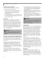
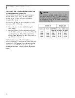
To load a CD into your CD-ROM drive, follow these
easy steps:

1. Push and release the eject button on the front of the

CD-ROM drive to open the holder tray. The tray will
come out of the notebook a short distance.

2. Gently pull the tray out until a CD can easily be

placed in the tray.

3. Place the CD into the tray, label side up, with the

hole in the center of the CD. Snap the CD onto
the raised circle in the center of the tray.

4. Gently push the holder tray back in until you

hear a click.

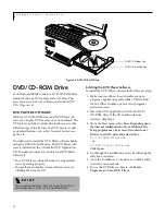
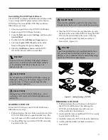
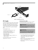
(Figure 4-5)

Figure 4-5 Loading/Ejecting a CD

CD Holder Tray

CD Eject Button

C A U T I O N

Do not operate your CD-ROM drive unless your
notebook is sitting on a flat surface. Using a CD
when the drive is not level may damage the drive
or prevent proper operation.

C A U T I O N

There may be a protective sheet in the tray when it was
shipped, please make sure it is removed before operating.

P O I N T

If you have disabled the Auto Insert Notification func-
tion, you will have to start the CD from your desktop,
as your notebook will not automatically recognize that
a CD has been loaded.

Summary of Contents for LifeBook C-4235

Page 1: ...S E R I E S Advanced Multimedia Discriminating Style User s Guide C ...

Page 2: ...trademark of Intuit Inc Sony MiniDisc is a trademark of Sony Electronics Inc Philips is a trademark of Koninklijke Philips Electronics N V Netscape Communicator is a registered trademark of Netscape Communications Corporation PC Doctor is a trademark of Watergate Software Inc LapLink is a registered trademark of Traveling Software Inc McAfee VirusScan is a trademark of NAI All other trademarks men...

Page 3: ...tandard modular jack type USOC RJ 11C which is FCC Part 68 compliant and a line cord between the modem and the telephone network with a minimum of 26AWG The REN is used to determine the number of devices that you may connect to your telephone line and still have all of those devices ring when your number is called Too many devices on one line may result in failure to ring in response to an incomin...

Page 4: ...nce with the certi fication standards does not prevent service degradation in some situations Repairs to telecommunication equipment should be made by a Canadian authorized maintenance facility Any repairs or alterations not expressly approved by Fujitsu PC Corporation or any equipment failures may give the telecommunication company cause to request the user to disconnect the equipment from the te...

Page 5: ...ue utilisé par ce périphérique afin de prévenir toute surcharge La terminaison d une boucle peut être consti tuée de n importe quelle combinaison de périphériques de sorte que le total de numéros de charge de tous les périphériques n excède pas 100 UL Notice For Authorized Repair Technicians Only A V E R T I S S E M E N T Pour assurer la sécurité les utilisateurs doivent vérifier que la prise de t...

Page 6: ...dicator 17 Battery Level Indicators 18 Battery Charging Indicators 18 DVD CD RW CD ROM Drive Access Indicator 18 Hard Drive or Removable Media Drive Access Indicator 18 Floppy Disk Drive Access Indicator 19 PC Card Access Indicators 19 NumLk Indicator 19 CapsLock Indicator 19 ScrLk Indicator 19 Keyboard Using the Keyboard 20 Numeric Keypad 20 Windows Keys 20 Cursor Keys 21 Function Keys 21 ErgoTra...

Page 7: ...g Your LifeBook 37 Power Management Suspend Resume Button 38 Suspend Mode 38 Save to Disk Mode 38 Idle Mode 40 Standby Mode 40 Display Timeout 40 Hard Disk Timeout 40 Windows 98 Power Management 40 Restarting the System 40 Power Off 41 SECTION FOUR Lithium ion Battery Recharging the Batteries 45 Replacing the Battery 46 Floppy Disk Drive Loading a Disk 47 Ejecting a Disk 47 Preparing a Disk for Us...

Page 8: ...ng the Problem 65 Specific Problems 65 Troubleshooting Table 66 Power On Self Test Messages 75 Emergency DVD CD RW CD ROM Tray Release 77 Modem Result Codes 77 Recovery CD ROM 78 SECTION SIX Care and Maintenance Fujitsu LifeBook 83 Batteries 84 Floppy Disks and Drives 84 DVDs and CDs 85 PC Cards 85 SECTION SEVEN Specifications Configuration Label 89 Microprocessor 90 Memory 90 Video 90 Audio 90 Ma...

Page 9: ...L i f e B o o k C S e r i e s ...

Page 10: ...1 P r e f a c e Section One Preface About This Guide 3 Fujitsu PC Contact Information 3 Warranty 3 ...

Page 11: ...2 L i f e B o o k C S e r i e s S e c t i o n S e v e n ...

Page 12: ...jitsu com Before you place the call you should have the following information ready so that the customer support representative can provide you with the fastest possible solution Product name Product configuration number Product serial number Purchase date Conditions under which the problem occurred Any error messages that have occurred Hardware configuration Type of device connected if any Fujits...

Page 13: ...4 L i f e B o o k C S e r i e s S e c t i o n O n e ...

Page 14: ...r 18 Hard Drive or Removable Media Drive Access Indicator 18 Floppy Disk Drive Access Indicator 19 PC Card Access Indicators 19 NumLk Indicator 19 CapsLock Indicator 19 ScrLk Indicator 19 Keyboard Using the Keyboard 20 Numeric Keypad 20 Windows Keys 21 Cursor Keys 21 Function Keys 21 ErgoTrac Pointing Device Clicking 22 Double Clicking 22 Dragging 23 ErgoTrac Control Adjustment 23 Volume Control C...

Page 15: ... c t i o n T w o Pre Installed Software Learning About Your Application Software 30 PC Doctor 30 LapLink Professional 30 Quicken 2000 Basic 30 McAfee VirusScan 30 PMSet 98 30 Adobe Acrobat Reader 30 LifeBook Application Panel Software 30 ...

Page 16: ...d Application Restore CD Getting Started Guide User s Guide Product Registration card Product Catalog International Limited Warranty Brochure Getting Started with Microsoft Windows 98 Second Edition First Cabin Registration card and envelope Depending on your configuration these devices may also come with your notebook DVD software CD for models with DVD ROM drive CD RW Software CD for models with...

Page 17: ...avetable Zoomed Video support for full motion video acceleration Built in Pioneer bass reflex stereo speakers Built in mono microphone Stereo line in jack Stereo headphone jack Microphone jack Digital audio out Combination PC card slot accommodates 2 Type II or 1 Type III cards Fast IrDA 4Mbps compatible infrared port for wireless data transfer Integrated pointing device for superb cursor control ...

Page 18: ...SDRAM 128MB SDRAM Power Lithium ion battery Auto Airline Adapter AC Adapter PC Cards Ethernet 10 100 Modem 56K Global Access Modem 56K Additional Accessories Wireless Infrared Mouse Supported by Performance Models only Wireless Keyboard and Mouse Numeric Keypad Universal LAN Hub USB Digital Camera Monitor stand MindPath PocketPoint TeleAdapt 16 TeleCord Notebook Guardian Lock Carrying Cases Diplom...

Page 19: ...graphics Figure 2 3 See Display Panel on page 34 for more information Built in Microphone The built in microphone allows mono audio input Figure 2 3 Status Indicator Panel The Status Indicator Panel displays symbols that corre spond with a specific component of your notebook Figure 2 3 See Status Indicator Panel on page 17 for more information Display Panel Latch Display Panel Status Indicator Pan...

Page 20: ...in dual speakers allow for stereo sound Figure 2 3 Closed Cover Switch The closed cover switch turns off the LCD back lighting when the display panel is closed Figure 2 3 Keyboard A full size keyboard with dedicated Windows keys Figure 2 3 See Keyboard on page 20 for more information ErgoTrac The pointing device is a mouse like cursor control with two buttons Figure 2 3 See ErgoTrac Pointing Devic...

Page 21: ...r your notebook Figure 2 4 PC Card Slots The PC Card Slots allow you to install two Type II PC Cards or oneType III PC Card Figure 2 4 See PC Cards on page 54 for more information Lithium ion Battery Bay The battery bay contains the internal Lithium ion battery It can be opened for the removal of the battery when stored over a long period of time or for swapping a discharged battery with a charged...

Page 22: ...ack allows you to connect an external mono microphone Figure 2 5 See Microphone Jack on page 60 for more information Volume Control The volume control provides manual control of the sound level of all audio output Figure 2 5 See Volume Control on page 24 for more information DVD CD RW CD Drive Your notebook will have one of the following built in devices Figure 2 5 DVD drive See DVD CD ROM Drive o...

Page 23: ... details Some hotels have Digital PBX systems Be sure to find out BEFORE you connect your modem C A U T I O N The internal modem is designed to the ITU T V 90 standard Its maximum speed of 53000bps is the highest allowed by FCC and its actual connection rate depends on the line conditions The maximum speed is 33600bps at upload C A U T I O N The internal modem on all Fujitsu notebooks from Fujitsu...

Page 24: ... Figure 2 6 See Parallel Port on page 59 for more information External Monitor Port The external monitor port allows you to connect an external VGA or SVGA CRT monitor Figure 2 6 See External Monitor Port on page 61 for more information Infrared Port The fast IrDA compatible port allows you to communi cate with another IrDA compatible infrared device without a cable Figure 2 6 See Infrared Port on...

Page 25: ...ation that you will need to give your support representative It identifies the exact version of various components of your notebook Figure 2 7 See Configuration Label on page 89 for more information Lithium ion Battery Bay The battery bay contains the internal Lithium ion battery It can be opened for the removal of the battery when stored over a long period of time or for swapping a discharged bat...

Page 26: ...as been turned off with the power switch AC ADAPTER INDICATOR The AC Adapter indicator states whether your notebook is operating from the AC adapter the Auto Airline adapter or the batteries This icon has two different states that can tell you what power source your notebook is using On This means that either of the adapters are currently in use Off Power is only coming from the batteries and you ...

Page 27: ...tive See Auto Insert Notification Func tion on page 53 for more information HARD DRIVE OR REMOVABLE MEDIA DRIVE ACCESS INDICATOR The Hard Drive Access indicator states whether your internal hard drive or optional second hard drive is being accessed P O I N T If there is no battery activity the adapters are not connected and the power switch is Off the Battery Level indicators will also be off C A ...

Page 28: ...re tries to access a PC Card even if there is no card installed The number inside the indi cator refers to which PC Card slot is being accessed See PC Cards on page 54 for more information NUMLK INDICATOR The NumLk indicator states that the internal keyboard is set in ten key numeric keypad mode CAPSLOCK INDICATOR The CapsLock indicator states that your keyboard is set to type in all capital lette...

Page 29: ... enter decimal points using the keys designated as ten key function keys The keys in the numeric keypad are marked on the front edge of the key to indicate their secondary functions Figure 2 10 WINDOWS KEYS Your notebook has three Windows keys consisting of two Start keys and an Application key The two Start keys display the Start menu This button functions the same as your onscreen Start menu but...

Page 30: ...g FN allows you to toggle between video compensation and no compensation Video compensation controls spacing on the display When it is enabled displays with less than 1024 x 768 or 800 x 600 pixel resolution will still cover the entire screen FN F6 Pressing F6 repeatedly while holding FN will lower the brightness of your display FN F7 Pressing F7 repeatedly while holding FN will increase the brigh...

Page 31: ...d releasing a button To left click move the cursor to the item you wish to select press the left button once and then immediately release it To right click move the mouse cursor to the item you wish to select press the right button once and then immediately release it Figure 2 12 Figure 2 12 Clicking Cursor Cursor Control Left Button Right Button P O I N T An external mouse can be connected to eit...

Page 32: ...Properties dialog box There are four aspects of the ErgoTrac operation which you can adjust Buttons This tab lets you set up the buttons for right or left handed operation in addition to setting up the time interval allowed between clicks when double clicking Pointers This tab lets you set up the scheme for the cursor depending on its functionality Motion This tab lets you set up a relation betwee...

Page 33: ...volume control has no effect on the volume We recommend that you use the hardware volume controls to set the upper limit for the sound level and then make fine adjustments with the Volume Control on the Taskbar and individual application software SETTING THE HARDWARE VOLUME CONTROL 1 Turn the volume control knob to the right of your notebook to increase the volume 2 Turn the volume control knob to...

Page 34: ...SELECTOR SWITCH Located at the far left of the panel this switch allows you to select the function of the panel either as an Applica tion Launcher a CD Player or as a lock APPLICATION LAUNCH CD PLAYER BUTTONS When the selector switch is in the Application position pressing any of the buttons will launch a user defined application When the selector switch is in the CD Player position the buttons op...

Page 35: ...lication B or E mail buttons click on the tab for the button you would like to reconfigure for example Application A Click on Browse from Start Menu scroll down the list of applications click on the application you wish to launch with this button and then click OK The button will now launch the new application The Internet tab is different It comes set to launch your Windows 98 default Internet br...

Page 36: ...he mail software you want to use i e Outlook Express Netscape Messenger etc You can also adjust the LED blinking time The default setting is for 60 seconds after mail has been retrieved After the setup Dial Up Networking E mail E mail LED is completed you are ready to retrieve mail When you press the E mail button your system will establish connection with your provider check for and retrieve new ...

Page 37: ...ck on the track display area of the panel and a menu will appear which will allow you to select from a pull down menu On the same pop up are two other options Always on top and Continuous Play If you click on Always on top the desktop controls will always be seen on your screen no matter what other application you are running If you click on Continuous Play your CD Player will auto matically start...

Page 38: ...ayer desktop control panel adjusts the vol ume of the CD audio line only It does not adjust your notebook s master software volume control or the manual volume on the LifeBook notebook The CD player desktop control panel is designed to be displayed in High Color 16 bit or in True Color 24 bit or more If you have your notebook s display set for 256 colors or less CD Player will display in a basic m...

Page 39: ...e your VirusScan online help or manual for more infor mation on how and when to run this program PMSET 98 PMSet 98 allows you to monitor and manage your battery status See your PMSet 98 online help for more information on the correct way to use this program ADOBE ACROBAT READER The Adobe Acrobat Reader located in the Service and Support Software folder allows you to view navigate and print PDF fil...

Page 40: ...4 Closing the Display Panel 34 Starting Your LifeBook Power On 35 Boot Sequence 35 BIOS Setup Utility 35 Booting the System with Windows 98 36 Registering Your LifeBook 37 Power Management Suspend Resume Button 38 Suspend Mode 38 Save to Disk Mode 38 Idle Mode 40 Standby Mode 40 Display Timeout 40 Hard Disk Timeout 40 Windows 98 Power Management 40 Restarting the System 40 Power Off 41 ...

Page 41: ...32 L i f e B o o k C S e r i e s S e c t i o n T w o ...

Page 42: ...ing the Optional Auto Airline Adapter 1 Plug the DC output cable into the DC power jack on your notebook 2 Plug the Auto Airline adapter into the cigarette lighter of an automobile with the ignition key in the On or Accessories position OR 3 Plug the Auto Airline adapter into the DC power jack on an airplane seat Switching from AC Adapter Power or the Auto Airline Adapter to Battery Power 1 Be sur...

Page 43: ...dly will increase the brightness of the display Power Management Utility Adjusting the brightness using the Power Management changes the setting permanently 1 Double click the Battery Icon in the lower right corner of your display This will open the PMSet 98 Properties dialog box 2 Select the Power Control tab and adjust your LCD Backlighting to the desired level 3 Click OK or Apply to permanently...

Page 44: ...ormation is in the BIOS program Each time you power up or restart your notebook it goes through a boot sequence which displays a Fujitsu logo until your operating system is loaded During booting your notebook is performing a standard boot sequence including a Power On Self Test POST When the boot sequence is completed without a failure and without a request for the BIOS Setup Utility the system di...

Page 45: ...stration for Windows 98 with Microsoft and for your LifeBook Series note book with Fujitsu PC Corporation Windows License Agreement and Final Settings You have the opportunity to review the Windows 98 License Agreement and then your configuration file will be generated Getting Started Read the instructions on the screens carefully and fill in the information as directed You will be asked for such ...

Page 46: ... do not register during the Welcome process you can double click on the LifeBook Registra tion icon on your desktop and follow the instructions You may also complete the pre printed registration form and either Fax to 1 949 450 9140 Mail to Fujitsu PC Corporation 15355 Barranca Pkwy Irvine CA 92618 9520 Call 1 800 8fujitsu 1 800 838 5487 You may also register on our Web site www 8fujitsu com You w...

Page 47: ...otebook is fully operational If the indicator is both visible and flashing your notebook is in Suspend mode If the indicator is not visible at all the power is off or your notebook is in Save to Disk mode See Save to Disk Mode SUSPEND MODE Suspend or Standby mode in Windows 98 saves the contents of your notebook s system memory during periods of inactivity by maintaining power to critical parts Th...

Page 48: ...y is kept active during Suspend mode or the memory is transferred to the internal hard drive during Save to Disk mode P O I N T When PC Cards or external devices are in use Save to Disk mode cannot return to the exact state prior to suspension because all of the peripheral devices will be re initialized when the system restarts P O I N T The main advantage of using the Save to Disk function is tha...

Page 49: ...nWindows and BIOS setup utility See BIOS Setup Utility on page 35 for more information HARD DISK TIMEOUT The Hard Disk Timeout is another one of the power management parameters This feature saves power by turning off the hard drive if there is no hard drive activity for the user selected timeout period Any attempt to access the hard drive will cause it to restart automatically This feature is inde...

Page 50: ...ect the Shut Down option from within the Windows Shut Down dialog box 3 Click OK to shutdown your notebook If you are going to store your notebook for a month or more see Care and Maintenance Section P O I N T You may also use the Suspend Resume button to shut off your notebook To do so first press the Suspend Resume button to suspend your notebook Next press and hold the button again until your n...

Page 51: ...42 L i f e B o o k C S e r i e s S e c t i o n T h r e e ...

Page 52: ...sing the DVD Player Software 52 Using the DVD Player on Battery Power 52 Auto Insert Notification Function 53 PC Cards Installing PC Cards 54 Removing PC Cards 55 Memory Upgrade Module Installing a Memory Upgrade Module 56 To Remove a Memory Upgrade Module 57 Checking the Computer Recognition of New Memory Capacity 58 Device Ports Modem RJ 11 Telephone Jack 59 Parallel Port 59 Serial Port 59 PS 2 ...

Page 53: ...44 L i f e B o o k C S e r i e s S e c t i o n F o u r ...

Page 54: ...y completely before recharging The charge times will be significantly longer if your notebook is in use while the battery is charging If you want to charge the battery more quickly put your notebook into Suspend mode or turn it off while the adapter is charging the battery See Power Management on page 38 for more information on Suspend mode and shutdown procedure C A U T I O N Actual battery life ...

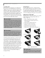
Page 55: ...cator to display the operating level available in that battery See figure 2 9 on page 18 If this display shows a Shorted Battery it means that the battery is damaged and must be replaced so it does not damage any other parts of your notebook REPLACING THE BATTERY With the purchase of an additional battery you can have a fully charged spare to swap with one that is not charged Figure 4 1 1 Have a c...

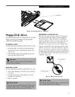
Page 56: ... so your notebook knows where to store information This preparation is called formatting or initializing a disk You will need to format new disks unless they are preformatted Please refer to your operating system manual for step by step instructions on formatting a disk To prevent accidental erasure of the data stored on a disk slide the write protect tab until a small hole is exposed This sets th...

Page 57: ...ith the hole in the center of the CD Snap the CD onto the raised circle in the center of the tray 4 Gently push the holder tray back in until you hear a click Figure 4 5 Figure 4 5 Loading Ejecting a CD CD HolderTray CD Eject Button C A U T I O N Do not operate your CD ROM drive unless your notebook is sitting on a flat surface Using a CD when the drive is not level may damage the drive or prevent...

Page 58: ...Save all data and close all open applications 2 From the Start menu select Settings and then select Control Panel 3 Double click the System icon This will open the System Properties dialog box 4 Select the Device Manager tab to display the device lists for your notebook 5 Click on the to the left of the CD ROM drive icon The treeview will expand to show the CD ROM drive manufacturer s name and mod...

Page 59: ...erform a complete system software recovery utilizing the recovery CD Installing the DVD Player Software To install the DVD Player software follow these easy step 1 Make sure you either close or disable any open programs applications and utilities This includes the MS Office Toolbar any anti virus programs and screensavers 2 Insert the DVD Application CD into the DVD CD ROM drive If the CD AutoRun ...

Page 60: ... push the holder tray back in until you hear a click Figure 4 7 Figure 4 7 Loading Ejecting a DVD CD REMOVING A DVD CD 1 Push and release the eject button on the front of the DVD CD ROM drive This will stop the DVD CD and the holder tray will come out of the notebook a short distance 2 Gently pull the tray out until the DVD CD can easily be removed from the tray 3 Carefully remove the DVD CD from ...

Page 61: ...reen 5 To Fast forward the movie click the button to forward to a specific portion of the movie or the button to jump to the ending credits 6 To Stop the movie click the button Exiting the DVD Player 1 Click on the Ulocated in the upper right corner of the title bar This will open a DVD Player dialog box 2 Click Yes to stop and exit the movie or No to close the DVD Player dialog box and return to ...

Page 62: ...ystem Properties dialog box 4 Select the Device Manager tab to display the device lists for your notebook 5 Click on the to the left of the DVD CD ROM drive icon The treeview will expand to show the DVD CD ROM drive manufacturer s name and model number 6 Double click on the DVD CD ROM drive manufac turer s name and model number This will open the DVD CD ROM drive manufacturer s name and model numb...

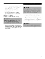
Page 63: ...1 or CardBus standards For further information refer to the instructions supplied with your PC Card INSTALLING PC CARDS PC Cards are installed in the PC Card slot To install a PC Card s follow these easy steps Figure 4 8 1 See your PC Card manual for specific instructions on the installation of your card Some PC Cards may require your notebook to be Off while installing them 2 Make sure there is n...

Page 64: ...liding the Lock button toward the rear of your notebook 3 Flip the Eject button towards the rear of your note book until it is fully extended and then push it in until it is flush with the notebook This will push the PC Card slightly out of the slot allowing you to remove the card C A U T I O N Windows has a shutdown procedure for PC Cards that must be followed before removing a card Please review...

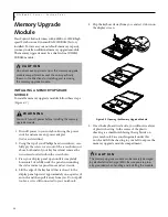
Page 65: ...se and set it aside 4 Lift the edge of the keyboard that is closest to the display panel upward approximately one quarter of an inch and then pull it away from you Do not pull too far as it is still connected to your notebook 5 Flip the keyboard away from you and set it down on the display screen Figure 4 9 Opening the Memory Upgrade Module 6 Once the keyboard is set aside you will notice a layer ...

Page 66: ...nel back into position 14 Replace the two screws and the screw covers REMOVING A MEMORY UPGRADE MODULE 1 Perform steps 1 through 6 of Installing a Memory Upgrade Module 2 Pull the clips sideways away from each side of the memory upgrade module at the same time Figure 4 11 3 While holding the clips out remove the module from the slot by lifting it up and pulling towards the rear of your notebook Fi...

Page 67: ...ent settings displayed See BIOS Setup Utility on page 35 for more information The System Memory and the Extended Memory capacity as detected by your notebook during the Power On Self Test POST are displayed at the bottom of the main menu screen The chart below shows you the possible displays that can be shown on the main menu screen P O I N T If the total memory displayed is incorrect check that y...

Page 68: ... the connector into the port until it is seated 3 Tighten the two hold down screws located on each end of the connector PS 2 PORT The PS 2 port allows you to connect an external keyboard and or numeric keypad and mouse In order to connect a PS 2 interface device follow these easy steps See figure 2 6 on page 15 for location 1 Align the connector with the port opening 2 Push the connector into the ...

Page 69: ...e IR Mouse receiver without the use of a cable See figure 2 3 on page 10 for location MICROPHONE JACK The microphone jack allows you to connect an external mono microphone Your microphone must be equipped with a 1 8 3 5 mm mono mini plug in order to fit into the microphone jack of your notebook In order to connect a microphone follow these easy steps See figure 2 5 on page 13 for location 1 Align ...

Page 70: ...ctronic devices to the line in jack The internal speakers might break if unexpected large sounds are inputted W A R N I N G Do not look into the connector There is a beam coming out from the SPDIF connector so please do not look into the connector when inserting the cable P O I N T The frequency of the digital sound output from the SPDIF output connector is fixed to 48KHz If a sampling rate conver...

Page 71: ...62 L i f e B o o k C S e r i e s S e c t i o n F o u r ...

Page 72: ... t i n g Section Five Troubleshooting Identifying the Problem 65 Specific Problems 65 Troubleshooting Table 66 Power On Self Test Messages 75 Emergency DVD CD RW CD ROM Tray Release 77 Modem Result Codes 77 Recovery CD ROM 78 ...

Page 73: ...64 L i f e B o o k C S e r i e s S e c t i o n F i v e ...

Page 74: ... possible solution Product name Product configuration number Product serial number Purchase date Conditions under which the problem occurred Any error messages that have occurred Hardware configuration Type of device connected if any See the Configuration Label on the bottom of your notebook for configuration and serial numbers See figure 2 7 on page 16 for location SPECIFIC PROBLEMS Using PC Doct...

Page 75: ...ones are plugged into your notebook Plugging in headphones disables the built in speakers remove the headphones BIOS audio settings are incorrect Set the BIOS setup utility to the default values within the Multimedia Device Configuration menu See BIOS Setup Utility on pag e35 for more information Software driver is not config ured correctly Refer to your application and operating system documentat...

Page 76: ...M drive is not installed The Windows DVD CD RW CD ROM auto insert notifica tion function is active and is checking to see if a DVD CD RW CD ROM is ready to run This is normal However you may disable this feature See Auto Insert Notification Function on page 53 for more information The Notebook fails to Auto Play a DVD movie The DVD Player software has not been installed Locate and install the DVD ...

Page 77: ...nd then turn it back on You have installed an external keyboard or mouse and it does not seem to work Your external device is not properly installed Re install your device See Device Ports on page 59 for more information Your operating system software is not setup with the correct software driver for that device Check your device and operating system docu mentation and activate the proper driver Y...

Page 78: ...ur notebook is not aware of its installation Close the application and restart your notebook Your software may not have the correct software driver active See your software documentation and activate the correct driver You may have the wrong I O address selected for your device See your device documentation and software docu mentation to determine the required I O address Change the settings in th...

Page 79: ...er Failures You turn on your notebook and nothing seems to happen The installed primary battery is completely discharged there is no optional second battery installed or there is no Power adapter AC or Auto Airline installed Check the Status Indicator Panel to determine the presence and condition of the batteries See Status Indicator Panel on page 17 for more information Install a charged battery ...

Page 80: ... setup utility to adjust the timeout values to better suit your operation needs You are operating on battery power only and have ignored a low battery alarm until the batteries are all at the dead battery state and your machine has gone into Dead Battery Suspend mode Install a power adapter and then push the Suspend Resume button See Power Sources on page 33 for more information You have a battery...

Page 81: ...nge Shutdown and Startup Problems The Suspend Resume button does not work The Suspend Resume button is disabled from the Advanced submenu of the Power menu of the setup utility Enable the button from the setup utility You did not hold the button in long enough Hold the button longer This may need to be a few seconds if your application is preventing the CPU from checking for button pushes There ma...

Page 82: ... Problems The built in display is blank when you turn on your notebook Something is pushing on the Closed Cover switch Clear the Closed Cover switch See figure 2 3 on page 10 for location The notebook is set for an external monitor only Pressing F10 while holding down the FN key allows you to change your selection of where to send your display video Each time you press the combination of keys you ...

Page 83: ...t close A foreign object such as a paper clip is stuck betweenthe display and the keyboard Remove all foreign objects from the keyboard The Built in Display has bright or dark spots If the spots are very tiny and few in number this is normal for a large LCD display This is normal do nothing If the spots are numerous or large enough to interfere with your operation needs Display is faulty contact y...

Page 84: ...tact your support representative nnnn Extended RAM Passed Where nnnn is the amount of memory in kilobytes successfully tested Failing Bits nnnn The hex number nnnn This is a map of the bits at the memory address in System Extended or Shadow memory which failed the memory test Each 1 one in the map indicates a failed bit This is a serious fault that may cause you to lose data if you continue Contac...

Page 85: ...lace your keyboard but may be able to use an external keyboard until then Contact your support representative Monitor type does not match CMOS Run SETUP Monitor type not correctly identified in Setup This error probably means your BIOS is corrupted run the setup utility and set all settings to the default conditions If you still get this error contact your support representative Operating system n...

Page 86: ...em timer error The timer test failed The main clock that operates the computer is faulty Requires repair of system board Contact your support representative for repairs UMB upper limit segment address nnnn Displays the address of the upper limit of Upper Memory Blocks indicating released segments of the BIOS memory which may be reclaimed by a virtual memory manager Video BIOS shadowed Video BIOS s...

Page 87: ...tion you will lose any software you have installed and any other files you created since you setup your computer You will have to re install any software that was not included with the computer when you bought it To Run the Emergency Recovery Program To use this portion of the CD ROM your notebook must Boot up upon power up or full system reset restart from the CD ROM drive 1 Insert the Emergency ...

Page 88: ...y 9 Restart your notebook 10 Reset your boot device priority in the BIOS setup as desired Your notebook now has all of the software installed that was included when you received it from the factory You must now load any programs which you purchased and installed after you received your notebook If you chose the Format and Recover Hard Drive option you should now restore your data files If you perf...

Page 89: ...80 L i f e B o o k C S e r i e s S e c t i o n F i v e ...

Page 90: ...81 C a r e a n d M a i n t e n a n c e Section Six Care and Maintenance LifeBook Series Notebook 83 Batteries 84 Floppy Disks and Drives 84 DVDs and CDs 85 PC Cards 85 ...

Page 91: ...82 L i f e B o o k C S e r i e s S e c t i o n S i x ...

Page 92: ...re that there are no objects in the case pressing on the lid Never position your notebook such that the CD ROM or DVD drive is supporting the weight of the note book Do not drop your Fujitsu LifeBook Do not touch the screen with any sharp objects Cleaning your Fujitsu LifeBook Always disconnect the power plug Pull the plug not the cord Clean your Fujitsu LifeBook with a damp lint free cloth Do not...

Page 93: ...use an explosion or fire Do not drop puncture disassemble mutilate or incin erate the battery Recharge batteries only as described in this manual and only in ventilated areas Do not leave batteries in hot locations for more than a day or two Intense heat can shorten battery life Do not leave a battery in storage for longer than 6 months without recharging it Increasing Battery Life Power your Fuji...

Page 94: ...surface with a ballpoint pen or pencil Always use a felt pen If a DVD CD is subjected to a sudden change in tem perature cold to warm condensation may form on the surface Wipe the moisture off with a clean soft lint free cloth and let it dry at room temperature DO NOT use a hair dryer or heater to dry DVD CDs If a DVD CD is dirty use only a DVD CD cleaner or wipe it with a clean soft lint free clo...

Page 95: ...86 L i f e B o o k C S e r i e s S e c t i o n S i x ...

Page 96: ...Section Seven Specifications Configuration Label 89 Microprocessor 90 Memory 90 Video 90 Audio 90 Mass Storage Device Options 90 Features 90 Device Ports 91 Keyboard 91 Power 91 Dimensions and Weight 91 Environmental Requirements 91 ...

Page 97: ...88 L i f e B o o k C S e r i e s S e c t i o n S e v e n ...

Page 98: ...III with SpeedStep Technology 500 MHz Celeron 450 MHz AMD K6 2 Display 14 1 XGA TFT 14 1 XGA TFT 14 1 XGA TFT 12 1 SVGA TFT Memory 128MB 64MB 64MB 64MB Hard Drive 12GB 9GB 6GB 6GB DVD CD Built in DVD Built in DVD Built in CD ROM Built in CD ROM Floppy Disk Drive Built in Floppy Disk Drive Built in Floppy Disk Drive Built in Floppy Disk Drive Built in Floppy Disk Drive Modem 56K V 90 support 56K V ...

Page 99: ... Ohms Mono microphone jack 125 mVp p or less minimum impedance 10K Ohms Two built in speakers 28 mm diameter Stereo One built in monaural microphone MASS STORAGE DEVICE OPTIONS Floppy Disk Drive Built in 3 5 Floppy Disk Drive which accommodates 1 44MB or 720KB floppy disks Hard Drive 2 5 fixed hard drive One of the following built in devices CD ROM Drive 24x maximum 5 CD ROM drive DVD Drive 6x 5 D...

Page 100: ...unction keys 12 F1 through F12 Feature extension key Fn Three Windows keys two Start keys and one application key Key pitch 19 mm Key stroke 3 mm Built in ErgoTrac pointing device with left and right buttons Built in Palm Rest External Keyboard Support PS 2 compatible External Numeric Keypad Support PS 2 compatible External Mouse Support PS 2 compatible POWER Batteries One 9 cell Lithium ion batte...

Page 101: ...92 L i f e B o o k C S e r i e s S e c t i o n S e v e n ...

Page 102: ...93 G l o s s a r y Section Eight Glossary ...

Page 103: ...94 L i f e B o o k C S e r i e s S e c t i o n E i g h t ...

Page 104: ...e micro processor which is much faster to access than your system RAM and used in specially structured ways to make your overall data handling time faster CardBus A faster 32 bit version of the PC Card interface which offers performance similar to the 32 bit PCI architecture CD ROM Compact disc read only memory This is a form of digital data storage which is read optically with a laser rather than...

Page 105: ...onnection between electronic devices ESD Electro Static Discharge The sudden discharge of elec tricity from a static charge which has built up slowly Example the shock you get from a doorknob on a dry day or the sparks you get from brushing hair on a dry day Extended Memory All memory more than the 640KB recognized by MS DOS as system memory FCC Federal Communication Commission Floppy Disk A spinn...

Page 106: ...t application commands including driver programs into the exact form required by a specific brand and model of micro processor in order to produce the desired results from that particular equipment Parallel Port A connection to another device through which data is transferred as a block of bits simultaneously with a wire for each bit in the block and with other wires only for control of the device...

Page 107: ...technique of copying data or applications stored in ROM Read Only Memory into RAM Random Access Memory for access during actual operation RAM is much faster to access than ROM however ROM contents are not lost when power is removed Shadowing allows permanently stored information to be rapidly accessed SMART Self Monitoring Analysis and Reporting Technology SMART is an emerging technology that prov...

Page 108: ...ith the PS 2 series of personal computers VRAM Video Random Access Memory A memory dedicated to video display data and control WFM Wired for Management is Intel s broad based initiative to reduce the total cost of ownership TCO of business computing without sacrificing power and flexibility Write Protect Prevent alteration of the binary state of all bits in a storage media Example all information ...

Page 109: ...100 L i f e B o o k C S e r i e s S e c t i o n E i g h t ...
Page 110: ...lt in Speakers 66 C Cache Memory 95 CD ROM care 85 drive 48 loading 48 Clicking 22 COMM Port 95 Cursor 22 Cursor Keys 21 D DC Output Cable 33 DC Power Jack 33 Device Ports 59 DIMM 56 Disk care 84 ejecting 47 formatting 47 initializing 47 loading 47 preparing 47 write protect 47 Display 73 74 Display Panel 34 adjusting 34 brightness 34 closing 34 opening 34 power management 34 Display Timeout 40 Do...

Page 111: ...68 Hard Disk Timeout 40 Headphone Jack 61 I Idle Mode 40 Infrared Port 60 IrDA 60 K Keyboard 20 68 cursor keys 20 function keys 20 numeric keypad 20 windows keys 20 L LifeBook Application Panel CD player 27 configuring 26 control panel 28 E mail 26 27 LCD display 25 selector switch 25 M Memory capacity 58 extended 58 installing 56 removing 57 system 58 upgrade module 56 Memory Upgrade Module 68 Mi...

Page 112: ...stration 36 37 Restarting 40 RJ 11 59 S Save to Disk Mode 21 38 SDRAM 56 Serial Port 59 69 98 Shut Down 41 Software See Pre installed Software Standby Mode 40 Stereo Line in Jack 60 Suspend 98 Suspend Mode 38 Suspend Resume Button 38 72 T Troubleshooting 65 U Universal Serial Bus Port 60 USB 60 69 W Windows 36 37 certificate of authenticity 37 end user license agreement 37 product key 37 Windows k...

Page 113: ...demark of Fujitisu PC Corporation All other trademarks mentioned herein are the property of their respective own ers 2000 Fujitisu PC Corporation All rights reserved CUG 0100 FPC58 0365 01 Fujitsu PC Corporation 5200 Patrick Henry Drive Santa Clara California 95054 For more information call 1 877 FPCDIRECT or visit our Web site at www fujitsu pc com ...

Reviews: