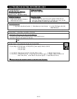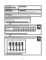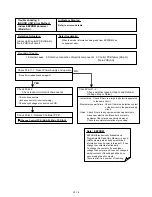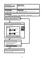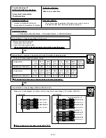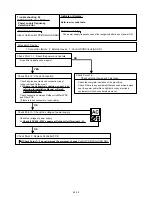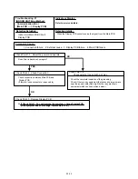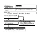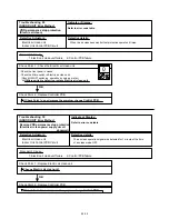
Trouble shooting 15
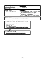
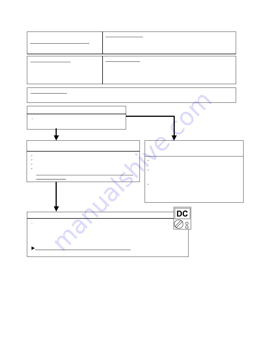
OUTDOOR UNIT Error Method:
Detective Actuators:
Detective details:
Forecast of Cause :
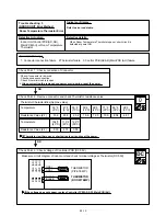
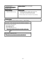
Check Point 3 : Check Filter PCB and Main PCB
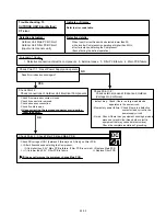
YES
NO
OK
Indicate or Display:
Refer to error code table.
CT error
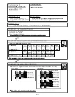
Outdoor Unit Main PCB Circuit
Outdoor Unit Filter PCB Circuit
(Input current sensor unit)
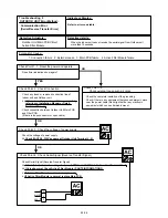
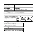
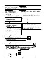
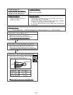
Check Point 2 :
Check connections of Outdoor Unit Electrical Components
Check if connector is removed.
Check if
the terminal connection
is loose.
Check erroneous connection.
Check if cable is open.
>>Upon correcting the removed connector or mis-wiring,
reset the power.
Check Point 1-2 :
Check external cause at Indoor and Outdoor
(Voltage drop or Noise)
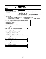
1. Defective connection of electric components 2. External cause 3. Filter PCB failure 4. Main PCB failure
Instant drop : Check if there is a large load electric
apparatus in the same circuit.
Momentary power failure : Check if there is a defective
contact or leak current in the
power supply circuit.
Noise : Check if there is any equipment causing harmonic
wave near electric line.(Neon bulb or electric
equipment that may cause harmonic wave)
Check the complete insulation of grounding.
Check Point 1-1 : Reset Power Supply and operate
Does Error indication show again?
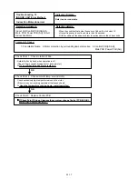
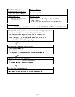
When Input Current Sensor has detected lower than 0A
while Inverter Compressor is operating at higher than 50Hz,
after 1minute upon starting the Compressor.
(Except during the defrost operation)
02-22
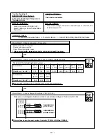
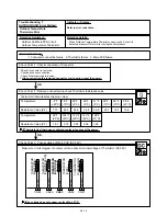
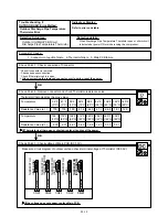
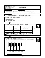
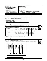
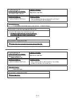
Check DC voltage of CN1 (between 2 (Brown) and 3 (Red)) on Filter PCB.
>> After 40seconds upon starting the Compressor,
If it is higher than 0.2V, Main PCB is failure. (Filter PCB is normal) >> Replace Main PCB
>> If it is lower than 0.2V, Filter PCB is failure. >> Replace Filter PCB
If it does not improve the symptom, change Main PCB.
Summary of Contents for Inverter Halcyon ASU12RMLQ
Page 3: ...1 DESCRIPTION OF EACH CONTROL OPERATION R410A WALL MOUNTED DUCT CASSETTE type INVERTER MULTI ...
Page 26: ...2 TROUBLE SHOOTING R410A WALL MOUNTED DUCT CASSETTE type INVERTER MULTI ...
Page 76: ...3 REPLACEMENT PARTS R410A WALL MOUNTED DUCT CASSETTE type INVERTER MULTI ...
Page 77: ...REPLACEMENT PARTS 03 01 Models ASU9RMLQ ASU12RMLQ ASU18RMLQ INVERTER ...
Page 78: ...REPLACEMENT PARTS 03 02 Models ASU9RMLQ ASU12RMLQ ASU18RMLQ ...
Page 79: ...Model ARU9RML 03 03 REPLACEMENT PARTS ...
Page 80: ...Model ARU9RML 03 04 REPLACEMENT PARTS ...
Page 81: ...Models ARU12RML ARU18RML 03 05 REPLACEMENT PARTS ...
Page 82: ...Models ARU12RML ARU18RML 03 06 REPLACEMENT PARTS ...
Page 83: ...Models ARU9RML ARU12RML ARU18RML 03 07 REPLACEMENT PARTS ...
Page 84: ...40 Models AUU9RML AUU12RML AUU18RML REPLACEMENT PARTS ...
Page 85: ...41 Models AUU9RML AUU12RML AUU18RML CONTROL UNIT REPLACEMENT PARTS ...
Page 86: ...38 CASSETTE TYPE DECORATION PANEL UTG UFUB W REPLACEMENT PARTS ...
Page 88: ...REPLACEMENT PARTS 03 08 Model AOU24RML AOU24RML1 ...
Page 89: ...REPLACEMENT PARTS 03 09 Model AOU24RML AOU24RML1 ...
Page 90: ...REPLACEMENT PARTS 03 10 Model AOU24RML AOU24RML1 ...
Page 92: ...REPLACEMENT PARTS 03 12 Model AOU36RML AOU36RML1 ...
Page 93: ...REPLACEMENT PARTS 03 13 Model AOU36RML AOU36RML1 ...
Page 94: ...REPLACEMENT PARTS 03 14 Model AOU36RML AOU36RML1 ...
Page 141: ...4 APPENDING DATA R410A WALL MOUNTED DUCT CASSETTE type INVERTER MULTI 1 PT CHART ...
Page 145: ...1116 Suenaga Takatsu ku Kawasaki 213 8502 Japan GS06082006 JUN 2006 Printed in Japan ...

