


143
CHAPTER 7 DETAILED EXECUTION INSTRUCTIONS
7.49
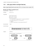
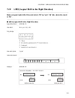
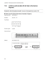
LSR2 (Logical Shift to the Right Direction)
Makes a logical right shift of the word data in "Ri" by "{u4 + 16}" bits, stores the result
to "Ri".
■
LSR2 (Logical Shift to the Right Direction)
Assembler format:
LSR2 #u4, Ri
Operation:
Ri >> {u4 + 16}
→
Ri
Flag change:
N: Cleared
Z: Set when the operation result is "0", cleared otherwise.
V: Unchanged
C: Holds the bit value shifted last.
Execution cycles:
1 cycle
Instruction format:
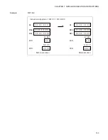
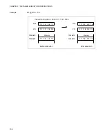
Example:
LSR2 #8, R3
N
Z
V
C
0
C
–
C
MSB
LSB
1
0
1
1
0
0
0
1
u4
Ri
R3
R3
0 0 0 0
0 0 F F
F F F F F F F F
N Z V C
CCR
CCR
N Z V C
0 0 0 1
0 0 0 0
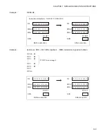
Instruction bit pattern :
1011 0001 1000 0011
Before execution
After execution
Summary of Contents for FR Family
Page 2: ......
Page 3: ...FUJITSU LIMITED FR Family 32 BIT MICROCONTROLLER INSTRUCTION MANUAL ...
Page 4: ......
Page 8: ...iv ...
Page 14: ...x ...
Page 36: ...12 CHAPTER 2 MEMORY ARCHITECTURE ...
Page 284: ...260 CHAPTER 7 DETAILED EXECUTION INSTRUCTIONS ...
Page 301: ...277 INDEX INDEX The index follows on the next page This is listed in alphabetical order ...
Page 314: ......