−
68
/
83
−
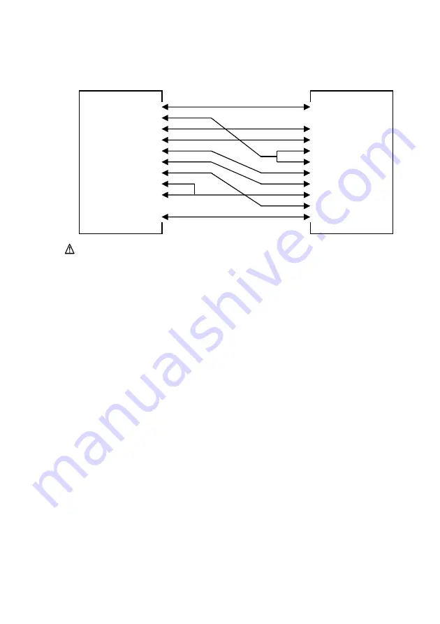
(3) Connection Cable
The connection setup shown in the following figure is recommended.
> DTR
20
9
RI <
> N.C
22
8
CTS <
>
7
RT
N.C
8
S <
>
6
DSR <
> DSR
6
5
SG <
> CT
SG
7
S
5
4
DTR <
> RTS
4
3
TXD <
> RXD
3
2
RXD <
> TXD
2
1
DCD <
> SG
1
Host
Printer
FG <
> FG
Caution: Supplying power from the interface connector is prohibited.


