background image

48

5.3

Adding and Deleting fi-5000N

When a fi-5000N is in the same subnet as the PC, it is automatically recognized and displayed in 
the List View. However, when it is in other subnet, add or delete with the following procedure.

Adding fi-5000N

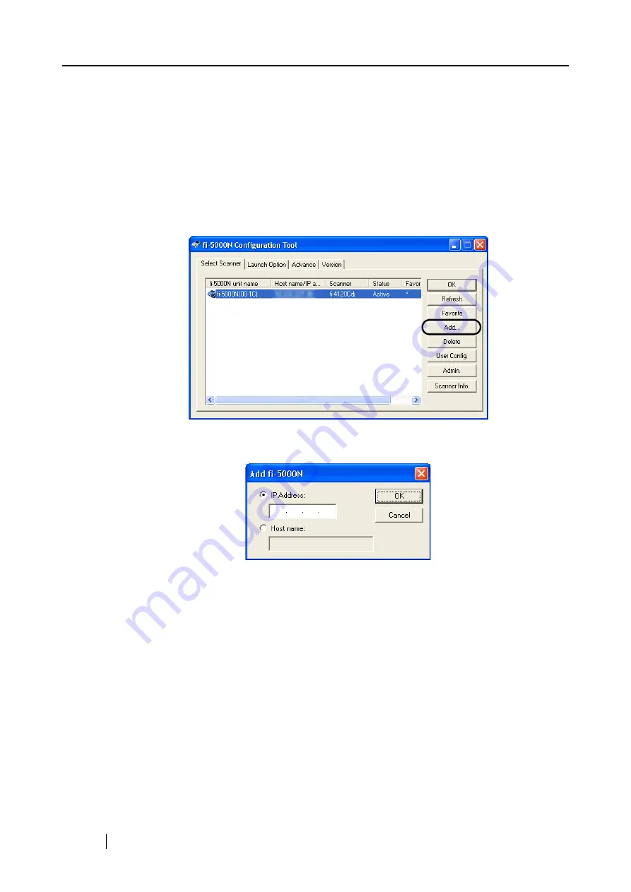
1. Click the [Add] button on the main screen of fi-5000N Configuration Tool.

2. Specify the IP address or host name of the fi-5000N to be added.

Select either the "IP Address:" or "Host Name", and enter the necessary information.
Example of entry: IP Address: 192.168.1.100

Host name: fi-5000n-00-01.fi-domain.xx.jp

Summary of Contents for fi-5000N

Page 1: ...Operator s Guide P3PC 1132 02EN 5000N ...

Page 2: ......

Page 3: ...3 1 3 Examples of Operation 4 Chapter 2 Names and Functions of Parts 7 2 1 Names of Parts 8 2 2 Keyboard 10 Chapter 3 Installing the fi 5000N 11 3 1 Installing the Scanner 12 3 2 Installing the fi 5000N 12 3 3 fi 5000N s Settings and Connecting to the Network 14 3 4 Changing the Language Setting 18 3 5 Automatic Turning Backlight Off Settings 19 3 6 Beep Sound Configuration 20 ...

Page 4: ...ll 21 31 4 3 Installing FUJITSU ISIS Scanner Driver 33 4 4 Configuring Scanning Application 36 4 5 Uninstalling the Scanner Driver and Scanning Application 39 Chapter 5 Installing and setting the fi 5000N Software 41 5 1 Installing fi 5000N Software 42 5 2 fi 5000N Software Overview 44 5 3 Adding and Deleting fi 5000N 48 5 4 Managing User Information of fi 5000N 51 5 5 fi 5000N Administrator Setti...

Page 5: ...7 7 1 Cleaning Materials 78 7 2 Parts to Clean and Cleaning Method 79 Chapter 8 Troubleshooting 81 8 1 Error Messages and Remedies 82 8 2 Troubleshooting 88 8 3 Items to Check Before Asking for Repair 90 8 4 Checking Labels on the fi 5000N 91 Chapter 9 Specifications 93 9 1 Basic Specifications 94 9 2 Installation Specifications 95 9 3 External Dimensions 96 APPENDIX Using User Authentication by F...

Page 6: ...iv ...

Page 7: ...e following measures Reorient or relocate the receiving antenna Increase the separation between the equipment and receiver Connect the equipment into an outlet on a circuit different from that to which the receiver is located Consult your dealer or an experienced radio TV technician FCC warning Changes or modifications not expressly approved by the party responsible for compliance could void the u...

Page 8: ...e personal domestic regular industrial and general purpose applications It has not been designed and manufactured for use in applications simply called high safety applications from here on that directly involve danger to life and health when a high degree of safety is required for example in the control of nuclear reactions at nuclear power facilities automatic flight control of aircraft air traf...

Page 9: ...United States and or other countries ISIS QuickScan and their respective logos are trademarks or registered trademarks of Pixel Translations a division of Captiva Software Corporation in the United States Adobe the Adobe logo and Acrobat are either registered trademarks of Adobe Systems Incorporated in the United States and or other countries Other product names are the trademarks or registered tr...

Page 10: ...re FUJITSU ISIS device driver QuickScan image capturing software WARNING This indication alerts operators to an operation that if not strictly observed may result in severe injury or death CAUTION This indication alerts operators to an operation that if not strictly observed may result in safety hazards to personnel or damage to equipment ATTENTION This symbol alerts operators to particularly impo...

Page 11: ...ailure and other troubles or an electric shock Use this device only at the indicated power voltage Do not connect to multiple power strips Use this device only at the indicated power voltage and current Improper power voltage and current might cause fire or electric shock Do not connect to multiple power strips Do not touch the AC cable with wet hands Do not touch the power plug with wet hands Doi...

Page 12: ...evice or the Maintenance Service Center Pay particular attention to this warning in households where there are small children Do not touch the inside of the device unless necessary Do not take apart or modify the device The inside of the device contains high voltage components Touching these components might cause electric shock or fire Do not use the device if there is a strange odor If you detec...

Page 13: ... far it can go into the power outlet Do not use the device immediately after moving it from a cold place into a warm room Do not use the device immediately after moving it from a cold place into a warm room Condensation may occur which might lead to operating errors Let the device dry about one or two hours before you use it Before moving the device disconnect the power plug from the power outlet ...

Page 14: ...ong period of time be sure to disconnect the power plug from the power outlet Do not install the device in direct sunlight Do not install the device under direct sunlight or near heating apparatus Doing so might cause excessive heat to build up inside the device which can cause device trouble or even fire Install the device in a well ventilated location ...

Page 15: ...1 fi 5000N Operator s Guide 1 Chapter1 Overview of fi 5000N 1 1 Overview 2 1 2 Features 3 1 3 Examples of Operation 4 ...

Page 16: ...ansmit scanned images to a computer over networks The fi 5000N makes it possible to scan documents without touching a computer at sites where scanning documents are required Furthermore only permitted operators can input images as this device has a built in fingerprint identification mechanism With the fi 5000N you can build up a system whereby you can scan documents easily and securely without op...

Page 17: ...twork becomes a reality with the utilization of USB 2 0 for the scanner interface and compatibility to 100BASE TX for the network interface 3 By leveraging your current system you can set up a distributed system easily With the TWAIN ISIS interface equipped you can make transition to remote scanning sys tem that utilizes your current system resources 4 Easy maintenance with the administrative tool...

Page 18: ...start scanning and to send the captured image data to a computer over the network This mode is called Push mode because the captured data is sent pushed form the scanner to the computer The operations are easy Set the document on to the scanner Perform the user authentication Press the Scan button With these 3 steps the captured data is sent to the computer You can try Push scan by following the p...

Page 19: ...ation of Scanner connection Settings of the connected scanner Adjustment of the scanner Consumables and counters of the scanner 3 Management of the Operator Means the maintenance of the operators who carry out the scanning The four maintenance actions are Registering new operator Changing operator information Deleting operator information Backing up Restoring operator information Operator Referred...

Page 20: ...6 ...

Page 21: ...fi 5000N Operator s Guide 7 2 Chapter 2 Names and Functions of Parts 2 1 Names of Parts 8 2 2 Keyboard 10 ...

Page 22: ... It is used for settings and PIN entry Finger Sensor Verifies finger s correct position Fingerprint Sensor Sensor used for fingerprint recognition Security Cable Slot Used for connecting the security cable Finger Guide Used to guide finger for correct positioning This guide is removable ESC ESC I D I D SET SET 7 8 9 4 5 6 1 2 3 0 Security Cable Slot Keyboard Sticker Fingerprint Sensor Finger Senso...

Page 23: ... Part Name Function DC Inlet Used for connecting the AC cable Power Switch Used for turning ON OFF the fi 5000N Network Connector Used for connecting a network cable LAN USB Connector Used for connecting a USB cable from a scanner DC Inlet Power Switch USB Connector Network Connector ...

Page 24: ...entication settings administrator rights required Automatic logout time settings administrator rights required Message display s backlight automatic light off administrator rights required Beep sound settings administrator rights required Host connection time out settings administrator rights required fi 5000N language settings administrator rights required Initialization of fi 5000N settings ATTE...

Page 25: ...s and Connecting to the Network 14 3 4 Changing the Language Setting 18 3 5 Automatic Turning Backlight Off Settings 19 3 6 Beep Sound Configuration 20 3 7 Pull Mode User Authentication Settings 21 3 8 Push Mode Automatic Logout Time Settings 23 3 9 Host Connection Time out 24 3 10 Displaying Device Information 25 3 11 Initialization of fi 5000N 26 ...

Page 26: ... its installation site Install this product near the scanner Install it in a place that does not affect the operation or maintenance of the scanner 2 Connect the AC adapter 1 Connect the AC cable to the AC adapter 2 Connect the AC adapter connector to the fi 5000N s DC inlet 3 Plug the AC cable into the outlet ATTENTION Use only the AC adapter and AC cable provided by the manufacturer ...

Page 27: ...SB cable provided with the scanner Correct operation with commercially available cables is not guaranteed ATTENTION The message Scanner is disconnected is displayed on the Message Dis play of fi 5000N if the scanner is not connected properly or if the power of the scanner is turned off Check the connection of the scanner when it hap pens Refer to the scanner product manual for details on turning o...

Page 28: ... cable to the network connector at the back of fi 5000N The following screen appears If the network support DHCP and the process goes success fully Place your finger on the sensor message appears ATTENTION To change the language setting refer to 3 4 Changing the Language Set ting page 18 HINT When the above screen remains still open the cover of the fi 5000N and press the ESC key The following scr...

Page 29: ...ork and press the ENT key The following screen appears 7 To obtain the IP address automatically from the DHCP Dynamic Host Configuration Protocol server select Use DHCP and press the ENT key To set the IP address manually select Use Static IP and press the ENT key If Use DHCP is selected It is not necessary to specify the IP address subnet mask and default gateway Go to step 11 If Use Static IP is...

Page 30: ...entry field Press the ENT key after you have entered the correct value To skip this step clear the currently displayed address or enter 0 0 0 0 on the entry field If the entered default gateway is correct the Speed Duplex Auto Negotiation settings screen appears ATTENTION Certain DNS servers and DHCP servers which do not support DNS update may cause host name resolution problems when DHCP is speci...

Page 31: ...lect Auto Negotiation if the hub supports auto negotiation function If auto negotiation function is not supported select the Speed Duplex that is supported by the hub The network communication may fail if the following settings are done When 100Base TX Full or Base TX Full is selected for a hub that only supports auto negotiation When Auto Negotiation is selected for a hub that does not support au...

Page 32: ...e Administrator s PIN personal iden tification number appears 3 Enter the Administrator PIN the default setting is 5000 and press the ENT key The following screen appears 4 With the L key select Change Language and press the ENT key The following screen appears 5 Press the K or L key to select the language and press the ENT key The following screen appears And the language setting is changed Setup...

Page 33: ...en tification number appears 3 Enter the Administrator PIN the default setting is 5000 and press the ENT key The following screen appears 4 With the L key select Auto Backlight Off and press the ENT key The following screen appears 5 To turn the backlight off automatically after a certain period of time select Auto off to leave the backlight s power always on select Always on and then press the EN...

Page 34: ... appears 3 Enter the Administrator PIN the default setting is 5000 and press the ENT key The following screen appears 4 With the L key select Beep On Off and press the ENT key The following screen appears 5 To set the beep sound on select Beep to set it off select mute and then press the ENT key The following screen appears With this the beep sound setting is done Setup Register Finger Change PIN ...

Page 35: ... PIN the default setting is 5000 and press the ENT key The following screen appears HINT There are 2 ways to perform scanning Push mode and Pull mode scan ning In Push mode scanning is started by pressing a scanner s button Scan or Send to button and the scanned image data is sent Pushed to the PC On the other hand in Pull mode scanning is started from the PC by using the scanning application whic...

Page 36: ...led the following screen will appear when the scanner driver is started up HINT About Pull mode scanning using ScandAll 21 When you start up ScandAll 21 open the TWAIN dialog box and click the Scan button the next message appears on monitor screen Please perform user authentication by fi 5000N before scanning This means fi 5000N is wait ing for fingerprint authentication Perform the user authentic...

Page 37: ...inistrator Setup and press the ENT key The screen to enter the Administrator s PIN personal iden tification number appears 3 Enter the Administrator PIN the default setting is 5000 and press the ENT key The following screen appears 4 With the L key select Auto logout time and press the ENT key The following screen appears 5 With the keyboard input the waiting time before logging out from 0 to 60 s...

Page 38: ...ect Administrator Setup and press the ENT key The screen to enter the Administrator s PIN personal iden tification number appears 3 Enter the Administrator PIN the default setting is 5000 and press the ENT key The following screen appears 4 With the L key select Host time out and press the ENT key The following screen appears 5 With the keyboard input the waiting time before the time out is perfor...

Page 39: ...ork settings refer to 3 3 fi 5000N s Settings and Connecting to the Network page 14 2 To display the network name of fi 5000N select Show Device Name For details about changing the network name refer to 5 5 fi 5000N Administrator Settings page 56 3 To display the firmware version select Firmware Version 4 To display the status of the connected scanner select Show Scanner Info The selected informat...

Page 40: ...d with this the initialization is completed Now configure the fi 5000N settings For details about the fi 5000N settings refer to 3 3 fi 5000N s Settings and Connecting to the Network page 14 ATTENTION Initialization will delete all uses information and the settings are reset to default Prior to performing initialization back up the user information by referring to 5 4 Managing User Information of ...

Page 41: ... 4 Configuring Scanning Application 36 4 5 Uninstalling the Scanner Driver and Scanning Application 39 Scanner Driver Application FUJITSU TWAIN 32 Scanner Driver ScandAll 21 For FUJITSU TWAIN 32 FUJITSU ISIS Scanner Driver QuickScan Pro For FUJITSU ISIS ATTENTION Although the scanner is bundled with its own scanner driver to connect the scanner to this product you must use the scanner driver bundl...

Page 42: ...r driver bundled with this product To uninstall previous versions uninstall Scanner Utility for Microsoft Windows from Add Remove Programs of the Control Panel We recommend you to check our website for the latest version of this driver Our site is http www fujitsu com global support computing peripheral scanners HINT Windows XP screenshots are used in this section as examples The windows and opera...

Page 43: ...r s Guide 29 Installing and Setting Driver 4 3 Click INSTALL PRODUCTS 4 Click TWAIN Driver on the window below 5 Select a language used for installation on Choose Setup Language window and click OK 6 Follow the instructions on the window to install the application ...

Page 44: ... restarted Installation of the scanner driver is completed ATTENTION To complete the installation successfully you must restart your PC HINT In order to use the scanner it is also necessary to have an application that complies with the TWAIN standard Use ScandAll 21 bundled with the fi 5000N To install ScandAll 21 refer to 4 2 Installing ScandAll 21 page 31 ...

Page 45: ... The FUJITSU TWAIN 32 scanner driver enables you to capture images with a FUJITSU image scanner fi series product 1 Insert the Setup CD ROM into the CD drive SETUP DISK START UP SCREEN appears 2 Click INSTALL PRODUCTS 3 Click ScandAll 21 on the window below ATTENTION When using Windows 2000 or Windows XP log on as a user with Administra tor privileges privileges of the administrator of your PC ...

Page 46: ...indow and click OK 5 Install the application following the instructions on the window 6 When the InstallShield Wizard Complete window appears click Finish ATTENTION For finishing the installation it may be necessary to restart your PC Follow the instructions on the window ...

Page 47: ...onnect the scanner to this product you must use the scanner driver bundled with this product We recommend you to check our website for the latest version of this driver Our site is http www fujitsu com global support computing peripheral scanners HINT Windows XP screenshots are used in this section as examples The windows and operations may slightly vary depending on your OS ATTENTION When using W...

Page 48: ... INSTALL PRODUCTS 4 Click ISIS Driver on the window below 5 Select a language used for installation on Choose Setup Language window and click OK 6 Follow the instructions on the window to install the application ...

Page 49: ...w appears click Finish Your PC will be restarted Do not remove the Setup CD ROM until your PC has com pletely restarted Installation of the scanner driver is completed HINT In order to use the scanner it is also necessary to have an application that complies with the ISIS standard you can install QuickScan Pro bundled with the scanner ...

Page 50: ...s displayed as FUJITSU Device Name on NET Select the name and click the Select button The selection of scanner is completed With the scanning application the scanner can be used in the same way as a scanner that is directly connected to a PC Pull mode Scanning HINT The selection method may differ from the description below according to the scanning application being used Refer to the manual or the...

Page 51: ...nner connected to fi 5000N is displayed as Fujitsu Device Name Select the name and click the Setup button The following window appears In this window the scanner name is displayed as Fujitsu Device Name On NET Select the name and click the OK button Selection of the scanner is completed With the scanning application the scanner can be used in the same way as a scanner that is directly connected to...

Page 52: ...ource dialog box When Pull mode scanning is enabled user authentication is required Per form user authentication with fingerprint or PIN To change the settings refer to 3 7 Pull Mode User Authentication Settings page 21 HINT For details on scanning documents and configuring the scanning applica tion refer to the Operator s Guide or QuickScan help supplied with the scanner ...

Page 53: ... or remove Programs screen which displays a list of the currently installed applications 4 Select the application to uninstall 1 When uninstalling FUJITSU TWAIN 32 Select Scanner Utility for Microsoft Windows 2 When uninstalling FUJITSU ISIS Select Fujitsu ISIS Drivers 3 When uninstalling ScandAll 21 Select ScandAll 21 5 Click the Change Remove button The confirmation window for uninstalling appea...

Page 54: ...40 ...

Page 55: ...5000N s Administrator The PCs used by the scanner s users This chapter describes the installation and operation procedures of the fi 5000N Software 5 1 Installing fi 5000N Software 42 5 2 fi 5000N Software Overview 44 5 3 Adding and Deleting fi 5000N 48 5 4 Managing User Information of fi 5000N 51 5 5 fi 5000N Administrator Settings 56 5 6 Managing Scanner Information 59 5 7 Settings of Launch Opt...

Page 56: ...ws XP Home Edition RAM 128 MB or higher Installing 1 Turn on the power of the PC and log on to Windows 2 Insert the Setup CD ROM into the CD drive SETUP DISK START UP SCREEN appears HINT Windows XP screenshots are used in this section as examples The windows and operations may slightly vary depending on your OS ATTENTION When using Windows 2000 or Windows XP log on as a user with Administrator rig...

Page 57: ...RODUCTS 4 Click fi 5000N Software on the window below 5 Select a language used for installation on Choose Setup Language window and click OK 6 Follow the instructions on the window to install the application 7 When the InstallShield Wizard Complete window appears click Finish Installation of the fi 5000N Software is completed ...

Page 58: ...b is selected is the main screen All kinds of administrative settings of fi 5000N can be done from this screen ATTENTION If Windows XP Service Pack 2 is installed Windows Security Alert dialog box may appear when starting up fi 5000N Software If Keep Blocking is selected with Windows firewall PC cannot communicate with fi 5000N In this case click Unblock to start the program Tabs List View The fi ...

Page 59: ...ame subnet as the PC is displayed automatically in the list To add an fi 5000N which is in other subnet use this button Delete button Deletes the selected fi 5000N from the list An fi 5000N cannot be deleted if it is in the same subnet as your PC User Config button Registers changes deletes user information of the selected fi 5000N Can be used only by the Operating Administrator The Administrator ...

Page 60: ...rwise no application will start up Target Specifies the file name of the application to be started Argument Configures the argument to be passed to the specified applica tion that is started With this function you can also add more actions than just start the scanning application when scanner button is pressed The argument that can be specified differs depending on the application being used Refer...

Page 61: ...mber on the PC Version Tab This tab shows the version information of the fi 5000N Configuration Tool Name of Item Function Trigger port PC Used to specify a trigger port number on the PC Default button Resets to the default number ATTENTION When changing the trigger port number on the PC you must also change the trigger port on the fi 5000N Refer to 5 5 fi 5000N Administrator Set tings page 56 If ...

Page 62: ...ther subnet add or delete with the following procedure Adding fi 5000N 1 Click the Add button on the main screen of fi 5000N Configuration Tool 2 Specify the IP address or host name of the fi 5000N to be added Select either the IP Address or Host Name and enter the necessary information Example of entry IP Address 192 168 1 100 Host name fi 5000n 00 01 fi domain xx jp ...

Page 63: ... with your network administrator and take one of the following measures for fi 5000N and PC For fi 5000N 1 Change to DNS server and DHCP server which support DNS update 2 Set the IP address lease time longer in DHCP server settings 3 Use static IP method For PC 1 Change to DNS server and DHCP server which support DNS update 2 Set the IP address lease time longer in DHCP server settings and registe...

Page 64: ...0N you want to delete from the List View of the main screen of fi 5000N Configuration Tool 2 Click the Delete button 3 Click Yes when the confirmation message appears HINT You cannot delete the fi 5000N which is in the same subnet as your PC ...

Page 65: ...er configu ration function To use this function the Administrator PIN is required How to Start 1 Select fi 5000N from the List View on the main screen on fi 5000N Configuration Tool and click the User Config button 2 The following screen appears Enter the Administrator PIN and click the OK button HINT The default Administrator PIN is 5000 You can use Admin button to change it Refer to 5 5 fi 5000N...

Page 66: ...ress and click the Enter button List View The user names registered in fi 5000N are displayed in a list User Name Enter the user name up to 16 characters You cannot leave it blank New PIN Fill in the User PIN up to 6 digits You cannot leave it blank Host name IP address Enter the IP address or the host name of the PC used by the user You cannot leave it blank Example IP Address 192 168 1 200 Host ...

Page 67: ...er the New PIN or the Host name IP address when the user name selected in the User Name column is displayed and click the Enter button 3 Click Yes when the confirmation message appears HINT It is possible to register a maximum of 32 users New PIN Fill in the User PIN up to 6 digits You cannot leave it blank Host name IP address Enter the IP address or the host name of the PC used by the user You c...

Page 68: ...ick the Backup button 2 Specify the destination and the file name and click the Save button when the follow ing screen appears 3 The screen to set the backup password for the file to be saved appears Enter the password up to 16 characters To confirm enter the password again 4 Click the OK button The user information is saved to a file ATTENTION This password is required when you do a restoration N...

Page 69: ...0N Software 5 Restoring User Information 1 Click the Restore button 2 Specify the files created at the backup procedure and click the Open button 3 The screen for password verification appears Enter the password set during backup 4 Click the OK button The user information is restored from the backup file ...

Page 70: ...or configuration function To use this function the Administrator PIN is required How to Start 1 Select an fi 5000N from the List View on the main screen on fi 5000N Configuration Tool and click the Admin button 2 The following screen appears Enter the Administrator PIN and click the OK button HINT The default Administrator PIN is 5000 ...

Page 71: ...follow the procedure below 1 Select the Change fi 5000N configuration check box 2 Enter a name in the edit box Enter up to 20 characters 3 Click the Apply button Changing the Trigger Port on the fi 5000N The currently selected trigger port number for the fi 5000N is displayed To change follow the procedures below 1 Select the Change fi 5000N configuration check box 2 Enter a number into the edit b...

Page 72: ...ure below 1 Select the Change PIN check box 2 Enter a new PIN into the edit box To confirm enter the PIN again Enter numerals up to 6 digits 3 Click the Apply button HINT The administrator PIN is required to use administrator functions of fi 5000N and fi 5000N Software This PIN can be changed from fi 5000N ...

Page 73: ... display the information of the scanner connected to an fi 5000N reset the consumables counter configure the power saving mode and adjust the offset setting How to Start Select an fi 5000N from the List View on the main screen on fi 5000N Configuration Tool and click the Scanner Info button The following screen appears To change the settings at the Device Set tab the Administrator PIN is required ...

Page 74: ...ware functions which may not be the same with the values that can be specified during scanning mentioned earlier The functions that can be achieved by the software are not displayed Also this tab does not appear if the scanner is in use or not connected If the tab does not appear exit the application that the scanner is using or check the connection and then display the tab ...

Page 75: ... when the scanner is in use or not connected If the tab does not appear exit the application that the scanner is using or check the connection and then display the tab To change the settings the Administrator PIN is required About Replacing Consumables The approximate number of scanned pages since the last consumables replacement and the remaining amount of imprinter ink are displayed in the red f...

Page 76: ... This message appears again after certain number of scans If you do not wish this message to be displayed select the This message not display again check box To stop scanning and replace the consumable click the Cancel button If the consumables are replaced reset the consumable counters by clicking the Clear buttons located in the Device Set tab About the Power Saving Settings Specifies the timer ...

Page 77: ...ng the flatbed you can specify the following modes to delete shadows on top edge and left edge of the paper Enable eliminating a dark area on the top of the image mode Enable eliminating a dark area on the left side of the image mode These modes may not appear depending on the scanner Vertical Magnification Adjustment You can change the magnification correction value for sub scan direction In case...

Page 78: ...lication after scanning ScanToFile only PROGRES 0 Hides the FUJITSU TWAIN 32 progressive indicator window SHOWUI X Displays or hides the FUJITSU TWAIN 32 setting window X 0 To hide X 1 To display X 2 Follows the setting done in ScandAll 21 SCANDEF XX Specifies the setting file of FUJITSU TWAIN 32 XX 00 99 NOSCNERR Hides the FUJITSU TWAIN 32 error messages NOAPPERR Hides the ScandAll 21 error messa...

Page 79: ...e example above is based on the default setting The 9 character which appears in Argument indicates a space You can assign 9 different functions to the Send to button By pressing the Function button on the scanner s operator panel the Send to button s function can be changed in the following order 1 J 2 J 9 J C J 1 J Function C cannot be used Name of Item Setting Button Scan Target C Program Files...

Page 80: ...ssing the Scan or Send to button on the scanner s operator panel fol low the steps below When the argument SHOWUI 0 is specified the following steps are not required 7 From the menu bar select Scan Option 8 Clear the TWAIN Dialog check box Configuring not to display any other setting screen If you do not want to let any other ScandAll 21 s setting screen appear after pressing the Scan or Send to b...

Page 81: ... Add or Remove Programs from the Start menu This displays the Add or Remove Programs screen which displays a list of the currently installed applications 4 Select fi 5000N Software 5 Click the Change Remove button The confirmation window for uninstalling appears 6 Click the OK button This executes the uninstallation ATTENTION Screen displays may vary slightly according to the operating system OS y...

Page 82: ...68 ...

Page 83: ...6 fi 5000N Operator s Guide 69 Chapter 6 User Authentication 6 1 Fingerprint Registration 70 6 2 User Authentication by Fingerprint 74 6 3 User Authentication by PIN 75 6 4 Changing the User s PIN 76 ...

Page 84: ... below 1 Open the Cover Confirm that the Place your finger on the sensor this indicates the Logout status is displayed on the fi 5000N Message Display 2 Then press the SET key on the fi 5000N s keyboard The following screen appears 3 Select Register Finger and press the ENT key The list of registered users on fi 5000N appears ESC ESC I D I D SET SET 7 8 9 4 5 6 1 2 3 0 Place your finger on the sen...

Page 85: ...TENTION The fi 5000N s Administrator must register the user in advance The user name registered by the Administrator in the fi 5000N Software will be displayed For details refer to 5 4 Managing User Information of fi 5000N page 51 HINT You can also select the registered user by entering user ID number 1 With the keyboard enter the user ID number 2 Press the ENT key The name of the user to log in w...

Page 86: ... screen appears 7 Remove your finger from the fingerprint sensor The following screen appears and the fingerprint verifica tions will be repeated twice 8 For verification procedure place the registered finger on the fingerprint sensor again If the first verification is successfully done the following screen appears 9 Second verification starts Look at the sticker inside of cover for finger placeme...

Page 87: ...ess has been completed the following message appears Then the message indicating that the fingerprint data is being saved is displayed Next the finishing registration message appears Press ENT key to finish the registration Second Verification is successful Saving fingerprint data Registration is successful OK ENT ...

Page 88: ...the fingerprint capturing begins 2 If the capturing of your fingerprint is successfully done a buzzer sounds and at the same time the following screen appears Remove your finger from the fingerprint sen sor 3 Next the identification of your fingerprint begins If the identification of your finger is successfully done a buzzer sounds and at the same time the following login screen appears Load the d...

Page 89: ...registered user with the K L keys and press the ENT key The next screen appears and the PIN is prompted 3 Enter the user s PIN and press the ENT key If the PIN does not match the message The PIN is incorrect appears and you are prompted to enter again 4 If the PIN matches the login screen appears HINT You can also select the registered user by entering user ID number 1 With the keyboard enter the ...

Page 90: ...as follows 3 Select the registered user with the K L keys and press the ENT key The next screen appears and the PIN is prompted 4 Enter the current PIN and press the ENT key If the PIN does not match the message The PIN is incor rect appears and you are prompted to enter again If the PIN matches the message New PIN appears 5 Enter the new PIN and press the ENT key For confirmation re enter the PIN...

Page 91: ...7 Chapter 7 Daily Care This chapter describes how to clean the fi 5000N Before you clean the fi 5000N turn off its power and unplug the AC adapter from the outlet 7 1 Cleaning Materials 78 7 2 Parts to Clean and Cleaning Method 79 ...

Page 92: ...you purchased the fi 5000N Cleaning Materials Parts Number Remarks Cleaner F1 or isopropyl alcohol CA99501 0013 1 bottle Moisten the cloth with this fluid and wipe the scanner clean Do not use it for cleaning printed characters logos and marking areas Lint free dry cloth Commercially available ...

Page 93: ...r The sensor might not function correctly in the following situations Clean the sensor surface on a regular basis Sensor surface is dirty with dust or any other dirt Sensor surface is wet There are dew drops on the sensor surface Clean the fingerprint sensor when the following problems occurs Cleaning the sensor might solve such problems The Display Message shows Sensor surface not clean Please wi...

Page 94: ...80 ...

Page 95: ...8 fi 5000N Operator s Guide 81 Chapter 8 Troubleshooting 8 1 Error Messages and Remedies 82 8 2 Troubleshooting 88 8 3 Items to Check Before Asking for Repair 90 8 4 Checking Labels on the fi 5000N 91 ...

Page 96: ...orted device is connected Check that the connected scanner is among the following fi 4120C 4120C2 4220C 4220C2 5110C 4530C Any other scanner and devices are not supported The network cable is disconnected Check the following Is the network cable LAN connected to the network Is the network cable LAN connected to this device Is the network cable LAN connected to a hub router etc Is the hub turned on...

Page 97: ...re a registered user Check whether it is a different finger that has been registered Register your finger again Unable to register fingerprint Please register again Refer to APPENDIX Using User Authentication by Fin gerprint page 1 and register your fingerprint again Unable to register this finger Register different finger The finger may not be in optimal condition extremely dry skin wounded etc f...

Page 98: ... PC which is to receive the scanned data is showing an error message follow the instructions ADF cover opened Scanner ADF paper chute hopper or imprinter cover is opened Confirm that scanner ADF paper chute hopper and imprinter are closed completely Press ENT key on fi 5000N keyboard If the PC which is to receive the scanned data is showing an error message follow the instructions No paper on ADF ...

Page 99: ... on FUJITSU TWAIN 32 User s Guide in the Setup CD ROM included in the scanner No print cartridge Confirm if the imprinter s print cartridge is installed cor rectly and the connection parts are clean and not contami nated Press ENT key on fi 5000N keyboard If the PC which is to receive the scanned data is showing an error message follow the instructions Message Remedies ...

Page 100: ...Buzzer frequency Nothing is displayed Blinks at 1 second intervals Nothing is displayed Blinks at 2 seconds intervals Memory Error Restart the device Failure of loading program Restart the device PCI Initial Error Restart the device Once long MACROM Read Error Restart the device Once long Hardware error of fingerprint sensor Restart the device Once long Failure of fingerprint sensor initialization...

Page 101: ...rvice provider No Message No Message 1 Temporary shortage of scanned data 12 LSI malfunction 2 EEPROM Error 13 Heater malfunction ADF Front 3 Fuse for ADF motor blown 14 Heater malfunction ADF Back 4 Background changeover unit failure 15 Heater malfunction Flatbed 5 Optical error 16 Motor fuse malfunction 6 Imprinter error 17 Lamp fuse malfunction 7 Fuse for Imprinter blown 18 Optical error ADF Fr...

Page 102: ...amp LED could be damaged If any of the following is observed Is the lamp on the network connector blinking orange Do messages appear on the Message Display Can the problematic fi 5000N be seen from the fi 5000N software Turn on the power again Nothing is displayed on the Message Display Is the power lamp of fi 5000N lighted up Turn off the power switch Check that the AC adapter and the power cable...

Page 103: ...Check whether there is a problem with the network cable or the net work such as hub router Fi 5000N does not appear in the Select Scanner tab of the fi 5000N Software Unable to communi cate over the network 1 Is the network cable connected 2 Is the Hub turned on 3 Is the fi 5000N s IP address set cor rectly 4 Is the fi 5000N turned on Check whether there is a problem with the network cable or the ...

Page 104: ...ing Labels on the fi 5000N page 91 Firmware version 0700 For details on how to check the firmware version refer to 3 10 Displaying Device Infor mation page 25 Date of purchase 2004 12 11 Symptoms There is no response when pressing the SET button Explain the symptom as much as possible Frequency of malfunction Once a week Type of OS Windows Windows XP with SP2 Connected Scanner Information Model Se...

Page 105: ...ations are samples of the product labels of the fi 5000N Label A Example Compliance of the device with specifications is shown Label B Example Information on the device is shown MODEL fi 5000N PART NO PA03368 B SER NO DATE 2004 11 MADE IN JAPAN 16V 0 5A 1 0kg MODEL fi 5000N PART NO PA03368 B SER NO DATE 2004 11 MADE IN JAPAN 16V 0 5A 1 0kg ...

Page 106: ...92 ...

Page 107: ...9 fi 5000N Operator s Guide 93 Chapter 9 Specifications This chapter lists the fi 5000N specifications 9 1 Basic Specifications 94 9 2 Installation Specifications 95 9 3 External Dimensions 96 ...

Page 108: ...C ENT L K Numeric key 0 9 Total 17 keys Fingerprint Sensor Static capacity method Resolution 500 dpi 256 x 300 pixels Finger Detection Sensor Type Infrared light photo reflector Memory Flash ROM 2 MB RAM 32 MB Scanner Interface USB 2 0 1 1 compatible USB 2 0 1 1 Auto recognition Supported scanners fi 4120C fi 4220C fi 4120C2 fi 4220C2 fi 5110C fi 4530C Network Interface LAN IEEE802 3 10BASE T IEEE...

Page 109: ...pth Width Height 176 mm 6 93 in 125 mm 4 92 in 62 mm 2 44 in Weight 1 0kg 2 2lb Input power Voltage 100 to 120 VAC 10 Phases Single phase Frequency 50 60 3Hz Power consumption 8 W or less Item Specification Ambient condition Device status Operating Not operating Temperature 5 to 35 C 41 to 95 F 20 to 60 C 4 to 140 F Humidity 20 to 80 8 to 95 ...

Page 110: ...96 9 3 External Dimensions The following shows the external dimensions of the fi 5000N Unit mm 6 93 in 4 92 in 2 44 in ...

Page 111: ...g the white position ing marks on the both sides of the fingerprint sensor crosses the base of your fingernail and press your finger to the sensor To confirm the correct way to place your finger click here to view the movie Make sure your finger covers the finger detection sensor Do not let your finger float away from the sensor To confirm the correct way to place your finger click here to view th...

Page 112: ...difficulties in capturing fingerprints Clean the sensor on a regular basis Sensor surface is dirty with dust or fat content from finger Sensor surface is moist with perspiration Sensor surface is moist with dew condensation If the following problems occur clean the sensor surface The situation may improve Processing Remove your finger from the sensor message keeps appearing Registration or authent...

Page 113: ...i 5000N fingerprint sensor area When you get accustomed to placing the finger correctly on the fingerprint sensor you can remove the Finger Guide To remove the Finger Guide follow the instructions below 1 Hold both sides of the Finger Guide 2 Squeeze the guide lightly to detach its pins 3 Lift the guide up and remove it from the fi 5000N ESC ESC I D I D SET 7 8 9 4 5 6 1 2 3 0 ...

Page 114: ...AP 4 ...

Page 115: ...0 Button 46 C Changing Administrator PIN 58 User Information 53 User PIN 53 Changing Language Setting 18 Cleaner F1 78 Cleaning Materials 78 Configuring Application FUJITSU ISIS 37 FUJITSU TWAIN32 36 Connecting to the Network 14 Cover 8 D DC Inlet 9 Delete button 45 Deleting fi 5000N 50 Users 54 Device Info Tab 60 Device Setting Tab 61 DHCP 15 Displaying Network settings 25 E ENT Key 10 ESC Key 10...

Page 116: ... Offset 63 Operator 5 P PIN 15 Power consumption 95 Power Saving Settings 62 Power Switch 9 Pull mode 4 21 Pull mode user authentication 21 Push mode 4 21 Push Mode Automatic Logout Time 23 Q QuickScan Pro 27 R Refresh button 45 Registering Users 52 Replacing Consumables 61 Reset to Factory default 26 Restoring User Information 55 S ScandAll 21 27 Scanner Drivers 27 Scanner Info button 45 Scanner ...

Page 117: ...47 Turn on the power 14 U Uninstalling fi 5000NSoftware 67 the Scanner Driver and Scanning Application 39 USB cable 13 USB Connector 9 User Authentication by PIN 75 User Config button 45 51 V Version Tab 47 W Waiting time for the host s connection 24 Weight 95 ...

Page 118: ...ts of this manual are subject to change without notice z PFU LIMITED is not liable whatsoever for any damages resulting from use of this scanner and procedures described in this manual profit loss due to defects and any claims by a third party fi 5000N Operator s Guide P3PC 1132 02EN Date of issuance February 2005 Issuance responsibility PFU LIMITED ...

Reviews: