background image

fi-4220C2 Image Scanner Getting Started


2

1.3 Operator Panel

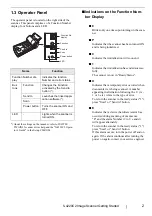
The operator panel is located on the right side of the 
scanner. This panel comprises  of a Function Number 
display, four buttons and a LED.

*) About the settings on the launcher, refer to FUJITSU 

TWAIN32 scanner driver help and the "fi-4220C2 Opera-
tor’s Guide" in the Setup CD-ROM.

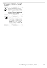
Indications on the Function Num-
ber Display

8

Blinks only one time upon turning on the scan-
ner.

P

Indicates that the scanner has been turned ON 
and is being initialized.

0

Indicates that initialization will soon end.

1

Indicates that initialization has ended success-
fully.
The scanner is now in "Ready Status". 

U

Indicates that a temporary error occurred when 
documents were being scanned. A number 
appearing in alternation following the U  (i.e., 
1 or 2, etc.) refers to the type of error.
To return the scanner to the ready status ("1"), 
press "Scan" or "Send to" button.

E

Indicates that a device (hardware) alarm has 
occurred during scanning of documents.
"E" and the alarm Number (2 to 9, c and d) 
will appear alternately.
To return the scanner to the ready status ("1"), 
press "Scan" or "Send to" button.
If this alarm occurs, turn the power off and on 
again. If the alarm continues after turning the 
power on again, contact your service engineer.

Name

Function

Function Number dis-
play

Indicates the function 
Number and error status.

But-
tons

Function

Changes the Function 
activated by the Send to 
button (*).

Send to

Launches the linked appli-
cation software (*).

Scan

Power button

Turns the scanner ON and 
OFF.

LED

-

Lights when the scanner is 
turned ON.

Function

Send to

Scan

LED

Power button

Function No.
display

Summary of Contents for fi-4220C2

Page 1: ...Getting Started fi 4220C2 Image Scanner P3PC E937 02EN Getting Started fi 4220C2 Image Scanner ...

Page 2: ......

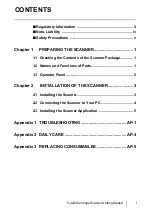
Page 3: ... 1 Checking the Contents of the Scanner Package 1 1 2 Names and Functions of Parts 1 1 3 Operator Panel 2 Chapter 2 INSTALLATION OF THE SCANNER 3 2 1 Installing the Scanner 3 2 2 Connecting the Scanner to Your PC 4 2 3 Installing the Scanner Application 5 Appendix 1 TROUBLESHOOTING AP 1 Appendix 2 DAILY CARE AP 4 Appendix 3 REPLACING CONSUMABLES AP 5 ...

Page 4: ...tlet on a circuit different from that to which the receiver is located Consult your dealer or an experienced radio TV technician FCC warning Changes or modifications not expressly approved by the party responsible for compliance could void the user s authority to operate the equipment Canadian DOC Regulations This digital apparatus does not exceed the Class B limit for radio noise emissions from d...

Page 5: ...id unexpected injury read the following carefully Doing the following actions may result in serious personal injuries Do not put the substance contained in the lamp in your mouth as it has mercury Do not breathe the chemical liquid contained in the scanner lamps Do not incinerate crush or shred the lamps or scanner parts Trademarks Microsoft Windows and Windows NT are registered trademarks of Micr...

Page 6: ...s manual are subject to change without notice in the interest of product improvement If the actual displayed screen differs from the screen examples in this manual operate by following the actual displayed screen while referring to the User s Manual of the scanner application you are using The screenshots in this manual were captured from FUJITSU TWAIN32 scanner driver ScandAll 21 Image Capturing ...

Page 7: ...ic shock and or equipment failure Use this scanner only at the indicated power voltage and current Improper power voltage and current might cause fire or electric shock Do not connect to multiple power strips Do not touch the power plug with wet hands Doing so might cause electric shock Wipe off any dust from metal parts on the power plug or metal fittings with a soft dry cloth Accumulated dust mi...

Page 8: ...at will support the weight of the scanner and other devices Do not block the ventilation ports Blocking the ventilation ports generates heat inside of scanner which may result in fire or scanner failure Do not place heavy objects on the scanner or use the scanner s surface top to perform other work Improper installation might cause injuries and equipment failure Firmly insert the power plug as far...

Page 9: ...he power outlet for safety Do not install the scanner under direct sunlight or near heating apparatus Doing so might cause excessive heat to build up inside the scanner which can cause scanner trouble or even fire Install the scanner in a well ventilated location When moving the scanner be sure to lock the shipping lock in order to prevent damages to the scanner When you perform cleaning make sure...

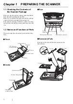
Page 10: ...ner and accessories with care 1 2 Names and Functions of Parts This section describes the scanner parts and their func tions Front Inside Rear Removable Parts Parts that can be removed from the scanner are dis played below ADF Automatic document feeder ADF paper chute Side guide ADF button Operator panel Stacker Flatbed Document holding pad Document cover Document bed Shipping lock located on base...

Page 11: ...s were being scanned A number appearing in alternation following the U i e 1 or 2 etc refers to the type of error To return the scanner to the ready status 1 press Scan or Send to button E Indicates that a device hardware alarm has occurred during scanning of documents E and the alarm Number 2 to 9 c and d will appear alternately To return the scanner to the ready status 1 press Scan or Send to bu...

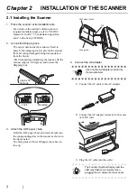
Page 12: ...ing the scanner tilt the scanner approx 30 degrees and release the Shipping lock 3 Attach the ADF paper chute Hold the ADF paper chute and insert its tabs into the corresponding slots in the scanner as shown in the figure below The Side guides of the ADF paper chute have to face up 4 Connect the AC adapter 1 Connect the AC cable to the AC adapter 2 Connect the AC adapter connector to the scan ner ...

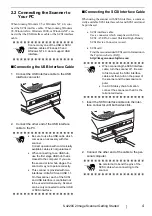
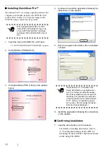
Page 13: ... both sides click 2 Connect the other end of the cable to the per sonal computer ATTENTION Connect only one of the USB or SCSI interface cables Windows 95 and Windows NT 4 0 do not support USB interface ATTENTION Be sure to use the USB cable which comes as an accessory with this scanner Correct operation with commercially available cables is not guaranteed When connecting to an USB hub use the fir...

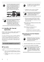
Page 14: ...JITSU TWAIN32 V8 ASPI Manager V4 01 or later is required generally comes with SCSI board products Installing the FUJITSU TWAIN32 Scanner Driver 1 Press the power button to turn on the scanner 2 Turn on your PC and log on to Windows HINT The factory default setting for SCSI ID is ID 5 If the SCSI ID of another SCSI device is set to the same ID either change the scanner s SCSI ID or SCSI ID of the o...

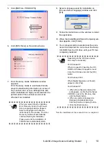
Page 15: ...ion is highly recommended the performance of the scanner would not be affected if not installed 8 Select a language used for installation on Choose Setup Language window and click OK 9 Follow the instructions on the window to install the application HINT The windows and operations may vary slightly depending on your OS ATTENTION This screen may not appear when the Autoplay setting of your PC is OF...

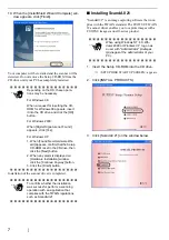
Page 16: ...ENTION Depending on the OS these opera tions may be necessary For Windows 98 When a request for inserting the CD ROM for Windows 98 appears insert it into the CD drive and click the OK button For Windows 2000 When Digital Signature not Found appears click Yes For Windows XP 1 When Found New Hardware Wiz ard appears confirm that the Setup CD ROM is set in the CD drive then click the Next button 2 W...

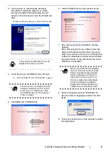
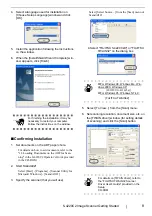
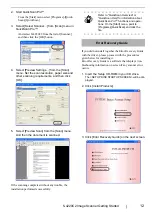
Page 17: ...Utility for Microsoft Windows ScandAll 21 3 Specify the scanner that you will use Select Select Source from the Scan menu of ScandAll 21 4 Select FUJITSU fi 4220C2dj or FUJITSU TWAIN32 on the dialog box 5 Select To View from the Scan menu 6 Set scanning resolution document size etc on the TWAIN driver window for setting details of scanning and click the Scan button ATTENTION For finishing the inst...

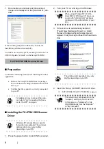
Page 18: ...dows 3 If the scanner is automatically detected Found New Hardware Wizard or Add Remove Hardware Wizard dialog box will appear Click Cancel to close the Wizard win dow 4 Insert the Setup CD ROM into the CD drive SETUP DISK START UP SCREEN appears HINT For details on how to connect the scan ner refer to 2 2 Connecting the Scan ner to Your PC on page 4 HINT Windows XP screenshots are used in this se...

Page 19: ...CD drive until your PC has completely restarted Now the installation of the scanner driver is completed ATTENTION When you select Yes for installing Error Recovery Guide the Choose Setup Language window appears Select a language and follow the instructions on the window The Error Recovery Guide will automatically continue finishing its installation Please wait until the installation of TWAIN drive...

Page 20: ...on following the instructions on the window Confirming Installation 1 Load the documents on to the scanner For details on loading documents refer to 1 2 Loading Documents on the ADF for Scanning in the fi 4220C2 Operator s Guide on the Setup CD ROM ATTENTION When using Windows NT 4 0 Win dows 2000 or Windows XP log on as a user with Administrator privileges privileges of the administrator of your ...

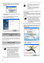
Page 21: ...tes without any trouble the installation performed successfully Error Recovery Guide If you did not install together the Error Recovery Guide with the driver please proceed with the procedures given below for installing it Error Recovery Guide is a software that displays trou bleshooting information on screen if any scanner error occurs 1 Insert the Setup CD ROM in your CD drive The SETUP DISK STA...

Page 22: ... the Install button when the screen below displays Then click the Install Acrobat 6 0 Standard button 3 Click the Next button when the following screen is displayed ATTENTION Adobe Acrobat 6 0 Standard is not supported by Microsoft Windows 95 Microsoft Windows 98 Except for Microsoft Windows 98 Second Edi tion Microsoft Windows NT4 0 Microsoft Windows Me To use Acrobat 6 0 with FUJITSU scanners FU...

Page 23: ...lation please read the Read me instructions on the screen of operation 2 For the Adobe Acrobat 6 0 operations please refer to the Adobe Acrobat 6 0 help ATTENTION Support and User registration for Adobe products Refer to the technical support informa tion stored in the Customer Support folder on Adobe Acrobat 6 0 Standard CD ROM Note that free person to person support is not available for this is ...

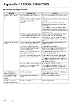
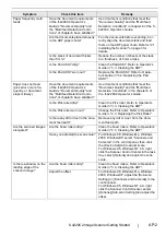
Page 24: ...te Is the ADF closed completely Close the ADF completely Is the USB cable or SCSI cable connected securely Connect the cable When a USB hub is used check the hub s power supply When using a SCSI interface Is SCSI ID set correctly Use the SCSI ID switch at the rear of the scanner to set the SCSI ID Does the Function Number display indicates an alarm or an error When the Function Number display indi...

Page 25: ...ent conditions that meet the Document Quality and the Multi feed Detection Conditions in the chapter 6 of the fi 4220C2 Operator s Guide Is the Pick roller dirty Clean the Pick roller Refer to Operator s Guide in 3 3 Cleaning the ADF Is the Pick roller worn out Change the Pick roller Refer to Operator s Guide in 4 3 Replacing the Pick Roller Is there any dirt or dust in the docu ment feed path Rem...

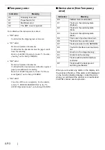
Page 26: ...ice alarm Non Temporary error When you encounter any alarm on the display turn the scanner off and on If the alarm is still displayed on the Function Number display contact the store where you purchased the scanner or an authorized FUJITSU scanner service provider Indication Meaning U0 Shipping lock error U1 Paper feed error U2 Multi feed error U4 The ADF cover is opened Indication Meaning E0 Flat...

Page 27: ...orm cleaning make sure that the inside of the scanner is free of any foreign object and be careful not to get your hand or the cloth caught on the pick spring metal part as a deformed pick spring metal part may cause injury Cleaning Materials Parts Number Remarks Cleaner F1 or isopropyl alcohol CA99501 0013 1 bottle Moisten the cloth with this fluid and wipe the scanner clean Lint free dry cloth C...

Page 28: ...used and cleaned The illustration below demonstrates the locations of the replacement parts Refer to Chapter 4 Replacing Con sumables fi 4220C2 Operator s Guide on the Setup CD ROM Replacing the Pad ASSY Replacing the Pick Roller WARNING The glass surface inside the ADF becomes hot during the operation Before replacing the consumables turn its power off and unplug the AC adapter from the outlet Wa...

Page 29: ......

Page 30: ...f this manual are subject to change without notice z PFU LIMITED is not liable whatsoever for any damages resulting from use of this scanner and procedures described in this manual profit due to defects and any claims by a third party fi 4220C2 Image Scanner Getting Started P3PC E937 02EN Date of issuance October 2009 Issuance responsibility PFU LIMITED ...

Reviews: