background image

System expansions

Replacing the lithium battery

In order to permanently save the system information, a lithium battery is installed to provide
the CMOS-memory with a current. A corresponding error message noti

fi

es the user when the

charge is too low or the battery is empty. The lithium battery must then be replaced.

Incorrect replacement of the lithium battery may lead to a risk of explosion!

The lithium battery may be replaced only with an identical battery or with
a type recommended by the manufacturer.

Do not dispose of lithium batteries with household waste. They must be disposed
of in accordance with local regulations concerning special waste.

Make sure that you observe the correct polarity when replacing the lithium
battery. The plus pole must be face up!

Lithiumbattery,

Replacing,

Replacing,

Replacing,lithiumbattery

Battery

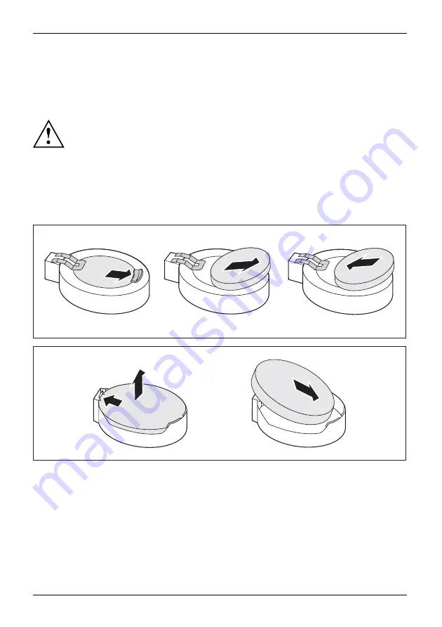
The lithium battery holder exists in different designs that function in the same way.

1

2

3

1

2

3

Press the catch in the direction of the arrow (1).

The battery jumps out of the holder slightly.

Remove the battery (2).

Push the new lithium battery of the identical type into the holder (3) and
press it down until it engages.

46

A26361-K1002-Z220-1-7619, edition 2

Summary of Contents for Esprimo C series

Page 1: ...ESPRIMO C Operating Manual ...

Page 2: ... enclosed Help Desk List or go to http ts fujitsu com support helpdesk html your sales partner your sales office Further information can be found in the Safety and Warranty manuals The latest information about our products useful tips updates etc is available from our website http ts fujitsu com ...

Page 3: ......

Page 4: ...Published by Fujitsu Technology Solutions GmbH A26361 K1002 Z220 1 7619 Edition 2 2009 08 Produced by XEROX Global Services ...

Page 5: ...ESPRIMO C Your ESPRIMO C 1 Important notes 3 Getting started 6 Operation 16 Troubleshooting and tips 22 System expansions 27 Technical data 47 Index 48 Operating Manual ...

Page 6: ...O World Corporation All other trademarks referenced are trademarks or registered trademarks of their respective owners whose protected rights are acknowledged Copyright Fujitsu Technology Solutions GmbH 2009 All rights reserved including rights of translation reproduction by printing copying or similar methods either in part or in whole Noncompliance is subject to compensation for damages All righ...

Page 7: ...ing external devices to the USB ports 13 Connecting the device to the mains voltage 14 Switching on for the first time installing the software 14 Switch on the monitor and the machine 15 Installing the software 15 Operation 16 Switch the device on 16 Switching off the device 16 Indicators on the device 16 Keyboard 18 Important keys and keyboard shortcuts 18 Settings in BIOS Setup 19 Property and d...

Page 8: ...ssible 5 1 4 inch drive 35 Installing and removing the hard disk drive 37 Installing and removing a Compact Flash module optional 40 Installing the Compact Flash module 40 Removing the Compact Flash module 41 Installing removing a SmartCard reader optional 42 Installing the SmartCard reader 42 Removing the SmartCard reader 42 Installing and removing a WLAN module optional 43 Installing the WLAN mo...

Page 9: ...in the BIOS Setup also allow you to protect access to your data e g by assigning password protection In addition systems with a SmartCard reader offer additional protection With certain operating systems DeskUpdate offers a simple and fast way to install the latest drivers and operating system upgrades using just a few mouse clicks DeskUpdate is included on the Drivers Utilities DVD Further inform...

Page 10: ...ommand used to start a program start exe This font indicates information that is displayed on the screen by a program e g Installation is complete This font indicates terms and texts used in a software interface e g Click on Save names of programs or files e g Windows or setup exe This font indicates cross references to another section e g Safety information cross references to an external source ...

Page 11: ...e device from the mains voltage To completely disconnect from the mains voltage remove the power plug from the power socket Replace the lithium battery on the mainboard in accordance with the instructions in the Replacing the lithium battery Page 46 chapter Caution components in the system can get very hot The activities described in these instructions must always be performed with the greatest ca...

Page 12: ...ing CEmarking Notes Electromagneticcompatibility Lowvoltagedirective The shipped version of this device complies with the requirements of EEC directives 2004 108 EC Electromagnetic compatibility and 2006 95 EC Low voltage directive CE marking for devices with radio component This equipment complies with the requirements of Directive 1999 5 EC of the European Parliament and Commission from 9 March ...

Page 13: ...se harmful interference to radio or television reception which can be determined by turning the equipment off and on the user is encouraged to try to correct the interference by one or more of the following measures Reorient or relocate the receiving antenna Increase the separation between equipment and the receiver Connect the equipment into an outlet on a circuit different from that to which the...

Page 14: ...p Preparingforfirstuse overview Preparingforuse Only a few steps are necessary to put your new device into operation for the first time Select a location for device and set up device Connecting external devices Check the voltage at the mains outlet and connect the device to an electrical outlet Switch the device on You will learn more about the individual steps in the following sections External d...

Page 15: ...device against dust humidity and heat Make sure that the device is adequately ventilated In order to avoid overheating do not cover the ventilation area of the monitor or the device Do not stack several devices on top of each other If you place a monitor on the device it may weigh a maximum of 25 kg Make sure that you do not block any ventilation slots on the device Depending on the location of yo...

Page 16: ...Pull off the foil from the rubber plastic feet included in the pack of accessories Stick the rubber plastic feet to the underside of the casing In order to ensure a that the unit is stable the rubber plastic feet should be located in approximately the positions shown in the illustration Place the device vertically on the rubber plastic feet If necessary reconnect any cables that were previously di...

Page 17: ...underside If necessary disconnect the cables Place the device on its upper side on a sturdy flat and clean surface Stick the rubber plastic feet 1 to the underside of the casing To ensure a that the device is stable the rubber plastic feet should be fixed in similar positions to the ones shown in the illustration Place the device on the rubber plastic feet If necessary reconnect any cables that we...

Page 18: ...and the external devices Please make sure that you always observe the safety notes provided in Important notes Page 3 Plug all data communication cables into the appropriate sockets Plug all power cables into the grounded mains outlets USB devices are hot pluggable This means you can connect and disconnect USB cables while your device is switched on Additional information can be found in Connectin...

Page 19: ... Headphones Audio input Line in light blue Audioinput Linein Audio output Line out light green Audiooutput Lineout PS 2 mouse port green Mouseport PS 2mouseport USB Universal Serial Bus black UniversalSerialBus LAN LAN port LANport DVI interface Some of the connected devices require special software e g drivers refer to the documentation for the connected device and operating system Connecting a m...

Page 20: ... the keyboard Insert the flat rectangular USB plug of the keyboard cable into one of the device s USB ports USBport Connecting a PS 2 keyboard Use the supplied keyboard cable only ConnectingaPS 2keyboard Connecting Plug the rectangular connector of the keyboard cable into the rectangular socket on the underside or on the rear of the keyboard Plug the round plug of the keyboard cable into the keybo...

Page 21: ... you can connect and disconnect USB cables while your device is switched on Additional information can be found in the documentation for the USB devices Connect the data cable to the external device Connect the data cable to one of the USB ports on your device Device drivers The external USB devices you connect to the USB ports usually require no driver of their own as the required software is alr...

Page 22: ...has been completed During installation the device may only be rebooted when you are requested to do so The installation will otherwise not be carried out correctly and the contents of the hard disk must be completely restored If the device is integrated into a network the user and server details as well as the network protocol are required during the software installation Contact your network admi...

Page 23: ...will start Installing the software During installation follow the on screen instructions Software Installing If anything is unclear regarding the data you are asked to input read the online Help in your operating system You will find more information on the system as well as drivers utilities and updates on the Drivers Utilities DVD and on the Internet under http ts fujitsu com support A26361 K100...

Page 24: ... switch for at least 4 seconds The device then consumes a minimum amount of energy The ON OFF switch does not fully disconnect the TV from the mains voltage To completely disconnect the mains voltage remove the power plug from the power socket If necessary switch the monitor off see the operating manual for the monitor Indicators on the device Indicators Device The indicators are located on the fr...

Page 25: ...saving mode The indicator does not light up The device is disconnected from the mains supply or is ready for operation If the device is ready it can be switched on with the ON OFF switch Hard disk indicator The indicator lights up when the hard disk drive of the device is accessed DVD indicator DVDindicator DVDindicator CD ROMindicator CD ROMdrive The indicator lights up when the DVD drive in the ...

Page 26: ...Details of other keys and keyboard shortcuts can be found in the documentation for the relevant application program ON OFFswitch Button On off switch optional Depending on the setting in the BIOS Setup the device can be switched on or off with this switch Some operating systems allow you to configure additional functions of the ON OFF switch in the Control Panel With some keyboards the ON OFF swit...

Page 27: ...ed to as Control or the Control key Alt Ctrl Del SysRq Ctrl Alt Del Keys keyboardshortcuts Ctrl Alt Del calls up the menu which you can use to shut down lock and log off from the computer You can also use this key combination to access the Windows Task Manager or change your Windows password Settings in BIOS Setup BIOSSetup Systemsettings BIOSSetup BIOSSetup BIOSSetup Setup In BIOS Setup you can s...

Page 28: ... unauthorized access e g Preventing unauthorised access to BIOS Setup Preventing unauthorised system access Preventing unauthorised access to the settings of boards with their own BIOS Preventing the system from booting from the diskette drive Issuing virus warnings Preventing the unauthorised writing of floppy disks Protecting BIOS from overwriting Protecting the device from being switched on by ...

Page 29: ...n be divided into user groups Users of a user group use SmartCards with the same permissions If you also want to use other security software in addition to SystemLock e g SMARTY please read the documentation on your security software beforehand SystemLock permissions You can initialize a SmartCard with one of the following permissions System The system starts following entry of the user PIN You ca...

Page 30: ...run the SystemDiagnostics program outputs a code e g DIFS code YXXX123456789123 Take a note of this DIFS code and the ID number of your device The ID number can be found on the type rating plate on the back of the casing For further clarification of the problem contact the Help Desk for your country see the Help Desk list or visit the Internet at http ts fujitsu com support For this please have re...

Page 31: ...any key on the keyboard or Deactivate the screen saver If necessary enter the appropriate password Brightness control is set to dark Adjust the brightness control For detailed information please refer to the operating manual supplied with your monitor Power cable not connected Switch off the monitor and the device Check that the monitor power cable is properly connected to the monitor and to a gro...

Page 32: ...rs If the menu for selecting the operating system appears press F8 Select Safe Mode or Safe Mode with Network Go to Start symbol Settings Control Panel Appearance and Personalization Personalization and enter the correct values for the connected monitor as described in the operating manual of the monitor Wrong monitor has been set under Windows 7 Restart the device Press F8 while the system is boo...

Page 33: ...ver is properly installed and is present when the application programme is started Detailed information can be found in the user guide for the mouse and application programme Time and or date is not correct Cause Remedy Time and date are incorrect Set the correct time and date within the operating system you are using or Set the correct time and or date in the BIOS Setup The lithium battery on the...

Page 34: ...iginal data in the event of any problems following installation you should backup your hard disk prior to installation Hard disk contents restoring The instructions can be found on the case of the Recovery DVD Tips Topic Tip Out of system resources Close unnecessary applications or Run the applications in a different order 26 A26361 K1002 Z220 1 7619 edition 2 ...

Page 35: ... print out the relevant sections of this chapter beforehand If further documentation was delivered with your device please also read this through carefully In addition before removing or installing system components please pay attention to the following The device must be switched off when installing removing the system expansions and may not be in energy saving mode Remove the power plug before o...

Page 36: ...p objects screwdrivers for leverage Boards with electrostatic sensitive devices ESD are identifiable by the label shown When handling boards fitted with ESDs you must always observe the following points You must always discharge static build up e g by touching a grounded object before working The equipment and tools you use must be free of static charges Only touch or hold the boards by the edge o...

Page 37: ...all cables from the casing Place the casing in a convenient working position If necessary unlock the casing Push the sliding locking mechanism past a slight resistance in the direction of the arrow to unlock the housing 1 2 Push the casing top cover as far as it will go approximately 20 mm in the direction of the arrow 1 and lift it off at an angle in the direction of the arrow 2 A26361 K1002 Z220...

Page 38: ...g mechanism back in the direction of the arrow until it engages Lock the casing again if necessary Return the system unit to its original position Reconnect the cables that you disconnected previously Installing and removing a board Please read the section Notes on boards You can only install low profile boards To install a board please follow the steps below Opening the retaining clip for the boa...

Page 39: ...n or EMC regulations which need to be complied with 1 2 Open the casing see Opening the casing Page 29 Open the retaining clip 1 Slide the slot cover upward out of the casing 2 Make the required settings on the board 2 1 Guide the board into the slot recess 1 Close the retaining clip 2 If necessary connect the cables to the module A26361 K1002 Z220 1 7619 edition 2 31 ...

Page 40: ...ant to install a new board reinstall the slot cover 1 2 Slide the slot cover downward into the rear panel of the casing 1 Close the retaining clip 2 Close the casing see Closing the casing Page 30 If you have installed or removed a PCI board check the relevant PCI slot settings in the BIOS Setup Change the settings as required Further information is provided in the PCI board documentation 32 A2636...

Page 41: ...ve cover Do not throw away the covers If you remove the drive again later you will need to fit the covers again cooling fire protection or EMC regulations which need to be complied with If you wish to install an accessible drive in an empty bay you must first remove the plastic drive cover Open the casing see Opening the casing Page 29 Lay the casing cover within easy reach on a non slip surface G...

Page 42: ...el and press the latches lightly into the corresponding brackets Close the casing see Closing the casing Page 30 Installing and removing the drive cage Removing the drive cage Drivecage Open the casing see Opening the casing Page 29 2 1 Fold up the drive cage at an angle 1 If a drive is present disconnect the connector of the data and power supply cables from the drive 2 Take out the drive cage fr...

Page 43: ...ible 5 1 4 inch drive Removing an accessible 5 1 4 inch slim drive Open the casing see Opening the casing Page 29 Remove the drive cage see Removing the drive cage Page 34 1 1 1 1 2 Remove the screws from the drive cage 1 Take the drive out of the drive cage 2 Install the drive cage again see Installing the drive cage Page 35 If you do not want to install a new drive you must refit the plastic dri...

Page 44: ...ng properly EMC electromagneticcompatibility If necessary remove the plastic drive cover see Removing the plastic drive cover Page 33 Remove the drive cage see Removing the drive cage Page 34 2 2 2 2 1 Slide the new drive as far as it will go into the drive cage 1 Fasten the screws 2 Install the drive cage again see Installing the drive cage Page 35 Connect the connector for the data and power cab...

Page 45: ...3 1 Fold up the drive cage 1 If there is a drive in the drive cage disconnect the data and power supply cables from the drive Fold up the hard disk cage 2 Pull the data and power supply cable off the hard disk 3 1 1 2 Press the two ends of the EasyChange rails together 1 and pull out the hard disk drive 2 A26361 K1002 Z220 1 7619 edition 2 37 ...

Page 46: ...hange rails for a future installation Close the casing see Closing the casing Page 30 Installing the hard disk drive Open the casing see Opening the casing Page 29 Make the required settings e g master setting on the drive Attach the EasyChange rails to the hard disk Fold up the hard disk cage 38 A26361 K1002 Z220 1 7619 edition 2 ...

Page 47: ...essary also attach the data cable at the main board Refer to the manual for the mainboard If necessary attach the connectors for the data and power cables at the drive Do not connect any cables Fold the hard disk cage downwards 2 Fold down the drive cage 3 Close the casing see Closing the casing Page 30 It may be necessary to modify the entry for the drive in the BIOS Setup A26361 K1002 Z220 1 761...

Page 48: ...age disconnect the data and power supply cables from the drive 1 1 1 Secure the Compact Flash module with the screws 1 to the carrier 1 Slide the Compact Flash module with the EasyChange rails into its bay until the carrier noticeably engages 1 Connect the connector for the data and power cables to the Compact Flash module Fold down the drive cage Close the casing see Closing the casing Page 30 40...

Page 49: ...t Flash cable connector from the mainboard Refer to the manual for the mainboard 1 1 2 Press the two ends of the EasyChange rails together 1 and pull out the hard disk drive 2 1 1 1 Loosen the screws 1 Remove the Compact Flash module from its bay Fold down the hard disk cage 2 Close the casing see Closing the casing Page 30 A26361 K1002 Z220 1 7619 edition 2 41 ...

Page 50: ...Otherwise you will not be able to insert the SmartCard from outside Connect the cable for the SmartCard reader to the mainboard and the SmartCard reader Refer to the manual for the mainboard Install the drive cage again see Installing the drive cage Page 35 Close the casing see Closing the casing Page 30 Removing the SmartCard reader SmartCardreader Open the casing see Opening the casing Page 29 1...

Page 51: ...designated bay 1 and secure it with the two screws 2 Make sure that you do not scratch the antenna on the front opening of the drive cage Connect the USB cable to the WLAN module Connect the USB cable of the WLAN module onto the corresponding connector on the mainboard Refer to the manual for the mainboard Install the drive cage again see Installing the drive cage Page 35 Close the casing see Clos...

Page 52: ...the connector on the mainboard Refer to the manual for the mainboard 1 1 2 Remove the screws 1 Pull the WLAN module out of the bay 2 together with the USB cable Make sure that you do not scratch the antenna on the front opening of the drive cage Install the drive cage again see Installing the drive cage Page 35 Close the casing see Closing the casing Page 30 44 A26361 K1002 Z220 1 7619 edition 2 ...

Page 53: ...e 29 1 Fold up the drive and hard disk cage Upgrading main memory Upgrade the memory according to the description in the manual for the mainboard Processor replacing Open the casing and remove the drive hard disk cage see Opening the casing Page 29 Processor replacing Replace the processor as described in the manual for the mainboard Re install the drive and hard disk cage and close the casing see...

Page 54: ...e manufacturer Do not dispose of lithium batteries with household waste They must be disposed of in accordance with local regulations concerning special waste Make sure that you observe the correct polarity when replacing the lithium battery The plus pole must be face up Lithiumbattery Replacing Replacing Replacing lithiumbattery Battery The lithium battery holder exists in different designs that ...

Page 55: ...c configuration approx 5 5 kg Environmental conditions Environment class 3K2 Environment class 2K2 DIN IEC 721 part 3 3 DIN IEC 721 part 3 2 Temperature Operation 3K2 15 C 35 C Transportation 2K2 25 C 60 C Condensation must be avoided during operation Clearance required to ensure adequate ventilation Without air vents With air vents min 10 mm min 200 mm The data sheet for this device provides furt...

Page 56: ... Contents of delivery 6 Cord see Cable 10 Ctrl Alt Del 19 Cursor keys 18 D Data protection 19 Device Checking rated voltage 14 Connecting 14 Connections 11 indicators 16 Setting up 7 Switching off 16 Switching on 16 Device drivers Parallel port 13 Device drivers Serial port 13 Device transporting 3 4 upgrades 27 Devices connecting 12 Devices connecting 13 Disposal 4 Drive cage installing 35 removi...

Page 57: ...rective 4 M Main memory 45 Mainboard Upgrades 45 Microphone jack 11 MicroSavers 20 Monitor connecting 11 Switching off 16 Switching on 16 Monitor port 11 Mouse port 11 Mouse connecting 12 N Note safety 3 Notes CE marking 4 important 3 Numeric keypad 18 O ON OFF switch 18 Operating position horizontal 9 Operating position vertical 8 Overview Device 1 P Packaging 6 Packaging unpacking 6 Parallel por...

Page 58: ...IOS Setup 19 Side cover 8 SmartCard reader installing 42 removing 42 SmartCard reader indicator 17 Software installing 14 15 System expansion 27 System settings BIOS Setup 19 System unit see Device 4 T Transportation 3 4 U Universal Serial Bus 11 Upgrades Mainboard 45 Upgrades device 27 USB devices connecting 13 USB port 12 USB port connecting devices 13 connecting keyboard 12 connecting the mouse...

Reviews: