


24
Technical Manual
D3081, D3131, D3082 (RX900 S1)
Features
3.2.1.1
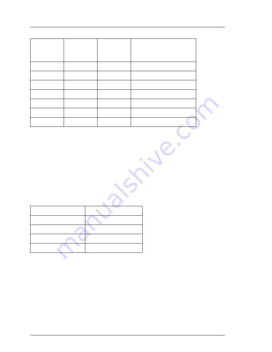
DIMM slot population order
CPUMEMRs are populated in four steps. In each step, four DIMM memory
modules are added. At least four DIMM memory modules must be installed on
CPUMEMR #1 and #2. CPUMEMRs #3 to #8 can be left empty.
Table 3
shows the DIMM slot population order for an individual CPUMEMR and
figure 2
maps the population order to the location of the DIMM slots on the
CPUMEMR.
2D
A
1
1
1C
A
0
0
2C
A
0
1
2A
B
0
1
1A
B
0
0
2B
B
1
1
1B
B
1
0
Population order
DIMM position
1
1B + 1D + 1F + 1H
2
1A + 1C+ 1E + 1G
3
2B + 2D + 2F + 2H
4
2A + 2C + 2E + 2G
Table 3: DIMM memory module population order for an individual CPUMEMR
DIMM slot
number
Millbrook
identifier
DDR
channel
number
DIMM memory module
number within the
same DDR channel
Table 2: DIMM memory module connection on the CPUMEMR


