background image

    1  1 Gbit/s Ethernet I/O Module    

113

E

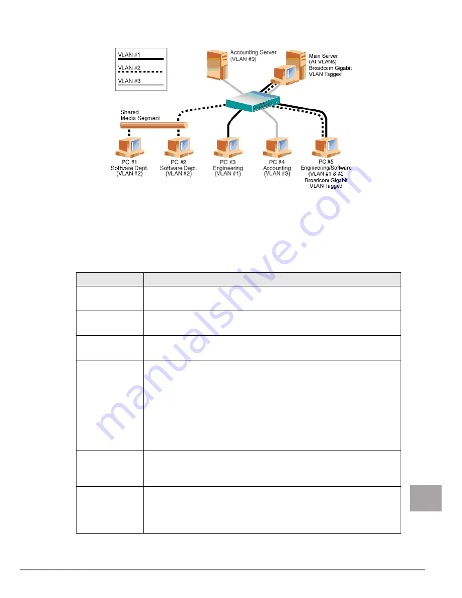
• Example of Servers Supporting Multiple VLANs with Tagging

"• Example of Servers Supporting Multiple VLANs with Tagging" (

J

pg.113)" shows an example 

network that uses VLANs. In this example network, the physical LAN consists of a switch, two 
servers, and five clients. The LAN is logically organized into three different VLANs, each 
representing a different IP subnet. The features of this network are described in "• Example VLAN 
Network Topology" (

J

pg.113). 

• Example VLAN Network Topology

Component 

Description

VLAN #1

An IP subnet consisting of the Main Server, PC #3, and PC #5. This subnet 
represents an engineering group. 

VLAN #2

Includes the Main Server, PCs #1 and #2 via shared media segment, and PC 
#5. This VLAN is a software development group. 

VLAN #3

Includes the Main Server, the Accounting Server and PC #4. This VLAN is 
an accounting group. 

Main Server

A high-use server that needs to be accessed from all VLANs and IP subnets. 
The Main Server has a Broadcom adapter installed. All three IP subnets are 
accessed via the single physical adapter interface. The server is attached to 
one of the switch ports, which is configured for VLANs #1, #2, and #3. Both 
the adapter and the connected switch port have tagging turned on. Because of 
the tagging VLAN capabilities of both devices, the server is able to 
communicate on all three IP subnets in this network, but continues to 
maintain broadcast separation between all of them. 

Accounting 
Server 

Available to VLAN #3 only. The Accounting Server is isolated from all traffic 
on VLANs #1 and #2. The switch port connected to the server has tagging 
turned off. 

PCs #1 and #2

Attached to a shared media hub that is then connected to the switch. PCs #1 
and #2 belong to VLAN #2 only, and are logically in the same IP subnet as 
the Main Server and PC #5. The switch port connected to this segment has 
tagging turned off. 

Summary of Contents for BX620

Page 1: ... the material provided This manual should be kept in an easy to access location for quick reference when using this product High Safety The Products are designed developed and manufactured as contemplated or general use including without limitation general office use personal use household use and ordinary industrial use but are not designed developed and manufactured as contemplated for use accom...

Page 2: ...drive Setup exe WARNING Ignoring this symbol could be potentially lethal CAUTION Ignoring this symbol may lead to injury and or damage this product The triangle mark emphasizes the urgency of the WARNING and CAUTION Details are described next to the triangle A barred circle warns against certain actions Do Not Details are described next to the circle A black circle indicates actions that must be t...

Page 3: ... R2 Standard x64 Edition Microsoft Windows Server 2003 R2 Enterprise x64 Edition Microsoft Windows 2000 Server Windows 2000 Server Microsoft Windows 2000 Advanced Server Red Hat Enterprise Linux ES v 3 for x86 Linux Red Hat Enterprise Linux AS v 3 for x86 Red Hat Enterprise Linux AS v 4 for x86 Red Hat Enterprise Linux ES v 4 for x86 Red Hat Enterprise Linux AS v 4 for EM64T Red Hat Enterprise Lin...

Page 4: ...k of Linus Torvalds in the United States and other countries Red Hat and all Red Hat based trademarks and logos are trademarks or registered trademarks of Red Hat Inc in the United States and other countries Other product names used are trademarks or registered trademarks of their respective manufacturers Other products are copyrights of their respective manufacturers All Rights Reserved Copyright...

Page 5: ...1 Broadcom Gigabit Ethernet Overview 119 4 2 Glossary 119 4 3 Teaming Concepts 121 4 4 Teaming Mechanisms 130 4 5 Types of Teams 133 4 6 Attributes of the Features Associated with Each Type of Team 136 4 7 Teaming and Other Advanced Networking Properties 138 4 8 General Network Considerations 140 4 9 Event Log Messages 151 5 Broadcom Advanced Control Suite 2 BACS2 156 5 1 BACS2 Overview 156 5 2 In...

Page 6: ...NET4 on the chassis 1 2 Specifications A server blade installed with this products and a server blade installed with a fibre channel expansion board cannot be installed to the same chassis When a Switch Blade is installed to network blade slot 3 or 4 NET3 or NET4 a FC Pass Thru Blade or FC Switch Blade cannot be installed at the same time Item Specifications Product ID PG LND201 Host bus specifica...

Page 7: ...refer to Broadcom Advanced Server Program BSAP Overview Jpg 109 in 1 3 3 Teaming Function Jpg 109 For a description of VLANs refer to 1 3 4 Virtual LAN Function Jpg 112 For instructions on configuring teaming and creating VLANs on Windows operating systems refer to 1 3 3 Teaming Function Jpg 109 1 3 2 Features The following is a list of this product features TCP Offload Engine TOE Single chip solu...

Page 8: ... CPU for more important tasks such as application processing This product s network adapter s TOE function allows simultaneous operations of up to 1024 fully offloaded TCP connections The TOE support on the adapter significantly reduces the host CPU utilization while preserving the implementation of the operating system stack Broadcom Advanced Control Suite 2 BACS2 Broadcom Advanced Control Suite ...

Page 9: ...tual adapter A team can consist of two to eight network interfaces and each interface can be designated as a primary interface or a standby interface standby interfaces can be used only in a Smart Load Balancing and Failover type of team and only one standby interface can be designated per SLB team If traffic is not identified on any of the adapter team member connections due to failure of the ada...

Page 10: ... correctly configured for 802 3ad link configuration errors are detected and noted With this mode all adapters in the team are configured to receive packets for the same MAC address The outbound load balancing scheme is determined by our BASP driver The team link partner determines the load balancing scheme for inbound packets In this mode at least one of the link partners must be in active mode G...

Page 11: ...I protocols is listed below The Smart Load Balancing type of team works with all Ethernet switches without having to configure the switch ports to any special trunking mode Only IP traffic is load balanced in both inbound and outbound directions IPX traffic is load balanced in the outbound direction only Other protocol packets are sent and received through one primary interface only Failover for n...

Page 12: ...Channel Bonding refer to http www redhat com docs manuals enterprise RHEL 3 Manual ref guide s1 modules ethernet html Teaming and Large Send Offload Checksum Offload Support Large Send Offload LSO and Checksum Offload are enabled for a team only when all of the members support and are configured for the feature 1 3 4 Virtual LAN Function VLAN Overview Virtual LANs VLANs allow you to split your phy...

Page 13: ...his VLAN is an accounting group Main Server A high use server that needs to be accessed from all VLANs and IP subnets The Main Server has a Broadcom adapter installed All three IP subnets are accessed via the single physical adapter interface The server is attached to one of the switch ports which is configured for VLANs 1 2 and 3 Both the adapter and the connected switch port have tagging turned ...

Page 14: ...ctions on adding a VLAN to a team refer to 5 5 Configuring Teaming Jpg 176 Adapters that are members of a failover team can also be configured to support VLANs Because VLANs are not supported for an Intel LOM if an Intel LOM is a member of a failover team VLANs cannot be configured for that team PC 3 A member of VLAN 1 PC 3 can communicate only with the Main Server and PC 5 Tagging is not enabled ...

Page 15: ...ade from the chassis refer to Blade Server System Unit Hardware Guide The circuit boards and soldered parts of internal options are exposed They can be damaged by static electricity Before handling them first touch a metal part of the server blade to discharge static electricity from your body Do not touch the circuitry on boards or soldered parts Hold the metallic areas or the edges of the circui...

Page 16: ...t s Ethernet I O Module in the expansion board slot in the BX620 S3 BX620 S4 Server Blade 2 1 2 Installation Procedure for the 1Gbit s Ethernet I O Module 1 Turn off the server blade where the 1Gbit s Ethernet I O Module will be installed 3 3 Turning Off the Server in Blade Server System Unit Hardware Guide 2 Touch a metal part of the chassis to discharge static electricity from your body 3 Remove...

Page 17: ...ecurely on the slot 6 Secure the 1Gbit s Ethernet I O Module with the screws Secure the 1Gbit s Ethernet I O Module with the three screws included with this product 7 Attach the top cover 7 2 Removing and Attaching the Top Cover in Server Blade User s Guide 8 Install the server blade to the chassis 4 2 Installing Server Blades in Blade Server System Unit Hardware Guide Expansion board slot Rear 1G...

Page 18: ... 2003 with Scalable Networking Pack SNP 3 1 1 Installing the LAN Drivers The installer will detect if SNP for Windows Server 2003 is installed on your machine If it is the installer will install the NDIS 5 2 driver which is necessary in order to use TOE If SNP for Windows Server 2003 is not installed on your machine the installer will install the NDIS 5 1 driver and you will not be able to use TOE...

Page 19: ...ced Control Suite BASP Broadcom Advanced Server Program intermediate driver DNS Domain Name Service G ARP Gratuitous Address Resolution Protocol Generic Trunking FEC GEC 802 3ad Draft Static Switch dependent load balancing and failover type of team in which the intermediate driver manages outgoing traffic and the switch manages incoming traffic HSRP Hot Standby Router Protocol ICMP Internet Contro...

Page 20: ...he standby team member is idle until a failover event for example loss of link occurs The intermediate driver BASP manages incoming outgoing traffic Smart Load Balancing SLB Switch independent load balancing and failover type of team in which the intermediate driver manages outgoing incoming traffic TCP Transmission Control Protocol UDP User Datagram Protocol WINS Windows name service WLBS Windows...

Page 21: ... differentiate traffic flows across applications The combination of the IP address and the TCP port number is called a socket Ethernet devices communicate with other Ethernet devices using the MAC address not the IP address However most applications work with a host name that is translated to an IP address by a Naming Service such as WINS and DNS Therefore a method of identifying the MAC address a...

Page 22: ...nfigured for fault tolerance This type of team works with any Ethernet switch and requires no trunking configuration on the switch The team advertises multiple MAC addresses and one or more IP addresses when using secondary IP addresses The team MAC address is selected from the list of load balance members When the system receives an ARP request the software networking stack will always send an AR...

Page 23: ...on of the number of clients that are connecting to the system through the team interface SLB receive load balancing attempts to load balance incoming traffic for client machines across physical ports in the team It uses a modified gratuitous ARP to advertise a different MAC address for the team IP Address in the sender physical and protocol address This G ARP is unicast with the MAC and IP Address...

Page 24: ...Trunking except that it uses the Link Aggregation Control Protocol to negotiate the ports that will make up the team LACP must be enabled at both ends of the link for the team to be operational If LACP is not available at both ends of the link 802 3ad provides a manual aggregation that only requires both ends of the link to be in a link up state Because manual aggregation provides for the activati...

Page 25: ...XOR hashing of the source and destination MAC address 4 3 3 Software Components Teaming is implemented via an NDIS intermediate driver in the Windows Operating System environment This software component works with the miniport driver the NDIS layer and the protocol stack to enable the teaming architecture refer to Process for Selecting a Team Type Jpg 129 The miniport driver controls the host LAN ...

Page 26: ...is supported for Gigabit Ethernet adapters in the IEEE 802 3 specification half duplex mode is not supported by the majority of Gigabit Ethernet adapter manufacturers Therefore half duplex mode will not be considered here Teaming across hubs is supported for troubleshooting purposes such as connecting a network analyzer for SLB teams only Switching Hub Unlike a repeater hub a switching hub or more...

Page 27: ...pology test 4 3 6 Supported Features by Team Type Comparison of Team Types provides a feature comparison across the team types Use this table to determine the best type of team for your application The teaming software supports up to eight ports in a single team and up to four teams in a single system The four teams can be any combination of the supported teaming types but each team must be on a s...

Page 28: ... IP No Yes IPX outbound traffic only Yes Yes Same MAC address for all team members No No Yes Yes Same IP address for all team members Yes Yes Yes Yes Load balancing by IP address No Yes Yes Yes Load balancing by MAC address No Yes used for no IP IPX Yes Yes 1 SLB with one primary and one standby member 2 Requires at least one Broadcom adapter in the team Link aggregation is not supported in the Bl...

Page 29: ...eric Trunking as the second choice and SLB teaming as the third choice when using unmanaged switches or switches that do not support the first two options if switch fault tolerance is a requirement however then SLB is the only choice refer to Process for Selecting a Team Type Jpg 129 Process for Selecting a Team Type No No No No Yes Yes Yes Do you need additional network bandwidth or fault toleran...

Page 30: ...ter The primary function of BASP is to balance inbound for SLB and outbound traffic for all teaming modes among the physical adapters installed on the system selected for teaming The inbound and outbound algorithms are independent and orthogonal to each other The outbound traffic for a particular session can be assigned to a given port while its corresponding inbound traffic can be assigned to a d...

Page 31: ...ical adapter will always be selected for outbound packets The exception is Address Resolution Protocol ARP which is handled differently to achieve inbound load balancing 4 4 3 Inbound Traffic Flow SLB Only The Broadcom intermediate driver manages the inbound traffic flow for the SLB teaming mode Unlike outbound load balancing inbound load balancing can only be applied to IP addresses that are loca...

Page 32: ...ress will go out through the same physical adapter If the packet uses TCP or UDP for the L4 protocol then the port number is added to the hashing algorithm so two separate L4 flows can go out through two separate physical adapters to the same IP address For example assume the client has an IP address of 10 0 0 1 All IGMP and ICMP traffic will go out the same physical adapter because only the IP ad...

Page 33: ...am is that it operates on any IEEE compliant switch and requires no special configuration Smart Load Balancing and Failover SLB provides for switch independent bidirectional fault tolerant teaming and load balancing Switch independence implies that there is no specific support for this function required in the switch allowing SLB to be compatible with all switches Under SLB all adapters in the tea...

Page 34: ...ts for the same MAC address Trunking operates on Layer 2 addresses and supports load balancing and failover for both inbound and outbound traffic The BASP driver determines the load balancing scheme for outbound packets using Layer 4 protocols previously discussed whereas the team link partner determines the load balancing scheme for inbound packets The attached switch must support the appropriate...

Page 35: ...nd the switch continually monitor their ports for link loss In the event of link loss on any port traffic is automatically diverted to other ports in the team Network Communications The following are the key attributes of Dynamic Trunking Failover mechanism Link loss detection Load Balancing Algorithm Outbound traffic is balanced through a Broadcom proprietary mechanism based on L4 flows Inbound t...

Page 36: ...ket management BASP Outgoing packet management BASP LiveLink support Yes Failover event Loss of link Failover time 500 ms Fallback time 1 5 s 1 approximate MAC address Different Multivendor teaming Yes 1 Make sure that Port Fast or Edge Port is enabled Feature Attribute User interface Broadcom Advanced Control Suite 2 BACS2 Number of teams Maximum 4 Number of adapters per team Maximum 8 Hot replac...

Page 37: ...ature Attribute User interface Broadcom Advanced Control Suite 2 BACS2 Number of teams Maximum 4 Number of adapters per team Maximum 8 Hot replace Yes Hot add Yes Hot remove Yes Link speed support Different speeds Frame protocol All Incoming packet management Switch Outgoing packet management BASP Failover event Loss of link only Failover time 500 ms Fallback time 1 5 s 1 approximate MAC address S...

Page 38: ...s a physical adapter property and has nothing to do with BASP and will be enabled on a particular adapter if the miniport driver for that adapter has flow control enabled All adapters on the team must support the property listed in Advanced Adapter Properties and Teaming Support Jpg 138 in order for the team to support the property Adapter Properties Supported by Teaming Virtual Adapter Checksum O...

Page 39: ...m size of 9000 bytes Though never formally adopted by the IEEE 802 3 Working Group support for jumbo frames has been implemented in this product The BASP intermediate driver supports jumbo frames provided that all of the physical adapters in the team also support jumbo frames and the same size is set on all adapters in the team IEEE 802 1Q VLANs In 1998 the IEEE approved the 802 3ac standard which...

Page 40: ...equest and ping replies in an SLB team with two active members All servers Blue Gray and Red have a continuous ping to each other Teaming Across Switches Without an Interswitch Link Jpg 141 is a setup without the interconnect cable in place between the two switches Teaming Across Switches With Interconnect Jpg 142 has the interconnect cable in place and Failover Event Jpg 142 is an example of a fa...

Page 41: ... and Gray to reach each other without any problems Note the additional entries in the CAM table for both switches The link interconnect is critical for the proper operation of the team As a result it is highly advisable to have a link aggregation trunk to interconnect the two switches to ensure high availability for the connection W2K Blue SLB Team 192 168 1 101 W2K3 Gray SLB Team 192 168 1 102 W2...

Page 42: ...49 C8 Eth 4 5E CA Eth 24 82 83 Eth 24 49 C9 Eth 24 5E C9 Eth 24 B0 30 Top Switch CAM Table Eth 1 82 83 Eth 2 49 C9 Eth 4 5E C9 Eth 24 82 82 Eth 24 49 C8 Eth 24 5E CA Eth 24 A2 12 Bottom Switch Port24 MAC Address Top Switch Port24 MAC Address 2 2 4 4 1 1 24 24 W2K Blue SLB Team 192 168 1 101 W2K3 Gray SLB Team 192 168 1 102 W2K Red SLB Team 192 168 1 100 ARP Table 100 49 C9 101 82 82 ARP Table 100 ...

Page 43: ...situation when you have redundant paths in your network STP detects disables network loops and provides backup links between switches or bridges It allows the device to interact with other STP compliant devices in your network to ensure that only one path exists between any two stations on the network After a stable network topology has been established all bridges listen for hello BPDUs Bridge Pr...

Page 44: ...s entries are removed from the table Traffic would then be flooded to all ports and re learned In this case it is beneficial to reduce the aging time This is the purpose of a topology change notice TCN BPDU The TCN is sent from the affected bridge switch to the root bridge switch As soon as a bridge switch detects a topology change a link going down or a port going to forwarding it sends a TCN to ...

Page 45: ...ng can be used with 10 100 hubs but it is only recommended for troubleshooting purposes such as connecting a network analyzer in the event that switch port mirroring is not an option 4 8 8 Hub Usage in Teaming Network Configurations Although the use of hubs in network topologies is functional in some situations it is important to consider the throughput ramifications when doing so Network hubs hav...

Page 46: ... network functionality is maintained Clients could be connected directly to the hub and fault tolerance would still be maintained server performance however would be degraded Team Connected to a Single Hub Generic and Dynamic Trunking FEC GEC IEEE 802 3ad FEC GEC and IEEE 802 3ad teams cannot be connected to any hub configuration These team types must be connected to a switch that has also been co...

Page 47: ...st have the same hardware revision firmware revision and software revision to be supported To be teamed adapters should be members of the same VLAN In the event that multiple teams are configured each team should be on a separate network Do not use the Locally Administered Address on any physical adapter that is a member of a team Remove any static IP address from the individual physical team memb...

Page 48: ...ot configured for Generic Trunking FEC GEC 802 3ad Draft Static types of teams Frequently Asked Questions Question Answer Under what circumstances is traffic not load balanced Why is all traffic not load balanced evenly across the team members The bulk of traffic does not use IP TCP UDP or the bulk of the clients are in a different network The receive load balancing is not a function of traffic lo...

Page 49: ...is part of a virtual adapter when the operating system loads PXE servers may operate over a virtual adapter What is the maximum number of ports that can be teamed together Up to eight ports can be assigned to a team What is the maximum number of teams that can be configured on the same server Up to four teams can be configured on the same server Why does my team loose connectivity for the first 30...

Page 50: ... using In all operating systems the most accurate method for checking the driver revision is to physically locate the driver file and check the properties Can SLB detect a switch failure in a Switch Fault Tolerance configuration No SLB can only detect the loss of link between the teamed port and its immediate link partner SLB cannot detect link failures on other ports Why does my team lose connect...

Page 51: ...k system memory resource usage The driver cannot allocate memory from the operating system Close running applications to free memory 2 Failed to allocate map registers The driver cannot allocate map registers from the operating system Unload other drivers that may allocate map registers 3 Failed to access configuration information Reinstall the network driver The driver cannot access PCI configura...

Page 52: ...igured for the selected line speed and duplex settings Informational message only No action is required 12 Medium not supported The operating system does not support the IEEE 802 3 medium Reboot the operating system run a virus check run a disk check chkdsk and reinstall the operating system 13 Unable to register the interrupt service routine The device driver cannot install the interrupt handler ...

Page 53: ...install the driver update to a newer driver run BACS2 diagnostics or replace the adapter Message Number Message Cause Corrective Action 1 Unable to register with NDIS The driver cannot register with the NDIS interface Unload any NDIS drivers 2 Unable to instantiate the management interface The driver cannot create a device instance Reboot the operating system 3 Unable to create symbolic link for t...

Page 54: ...Informational message only No action is required 11 Broadcom Advanced Program Features Driver is not designed to run on this version of Operating System The driver does not support the operating system on which it is installed Consult the driver release notes and install the driver on a supported operating system or update the driver 12 Hot standby adapter is selected as the primary adapter for a ...

Page 55: ...tion is required 16 Network adapter is activated and is participating in network traffic A physical adapter has been added to or activated in a team Informational message only No action is required 17 Network adapter is de activated and is no longer participating in network traffic The driver does not recognize the installed adapter Informational message only No action is required Message Number M...

Page 56: ...and perform certain tests diag nostics and analysis on a selected device by clicking a specific tab To the left of the Information Task pane is the Device Name pane which lists the names of the individual network adapters and the individual members of teams that have been created A third pane contains the Menu bar Broadcom Advanced Server Program BASP which runs within Broadcom Advanced Control Su...

Page 57: ...s Shows the resource settings for the selected adapter J 5 4 2 Resources pg 165 Hardware Shows the hardware information for the selected adapter J 5 4 3 Hardware pg 166 Advanced Shows the available properties and their values for the selected adapter J 5 4 4 Advanced pg 167 Network Test Confirms network connectivity to a remote station J 5 4 5 Network Test pg 170 Diagnostics Performs comprehensive...

Page 58: ...ave Windows Server 2003 with Scalable Networking Pack SNP The installer checks if SNP for Windows Server 2003 is installed on the machine If it is installed the installer installs the NDIS 5 2 driver which is necessary in order to use TOE If SNP for Windows Server 2003 is not installed on the machine the installer will install the NDIS 5 1 driver a user cannot use TOE Get the Broadcom Control Suit...

Page 59: ...For Windows Server 2003 x64 1 Start the following EXE file from the ServerStart Disc1 CD ROM attached to the BX620 S4 CD ROM drive PROGRAMS GENERAL Broadcom MgmtApps_x64 setup exe The installer starts up 2 Click Next License agreement window appears ...

Page 60: ...160 3 Click I accept the terms in the license agreement and click Next Custom Set up window appears 4 Click Next Proceed the installation by following the window instructions ...

Page 61: ...he OS is installed manually BACS2 will not be installed 1 Start the following EXE file from the ServerStart Disc1 CD ROM attached to the BX620 S4 CD ROM drive PROGRAMS GENERAL Broadcom MgmtApps setup exe The installer starts up 2 Proceed the installation by following the window instructions When the window below appears during the installation procedure check BASP and click Next ...

Page 62: ...e link status of the adapter and network connectivity To view this information for each network adapter click the name of the adapter listed in the Name pane Information about Intel LAN card is less comprehensive than the information provided for this product Some information may not be available for all network adapters Item Description MAC Address This is the physical MAC address that is assigne...

Page 63: ... Offload Capabilities The offload capabilities supported by the adapter LSO Large Send Offload prevents an upper level protocol such as TCP from breaking a large data packet into a series of smaller packets with headers appended to them CO Checksum Offload allows the TCP IP UDP checksums for send and receive traffic to be calculated by the adapter hardware rather than by the host CPU BASP State In...

Page 64: ...rresponds to a Not Active BASP state This condition does not apply to an adapter that is a standby member of a team The standby adapter may be working properly even though it is Not Active If the adapter icon shows a superimposed running yellow figure the adapter is connected and participating in the team correctly which corresponds to an Active BASP state If the adapter icon shows a superimposed ...

Page 65: ... MHz The bus clock signal frequency used by the adapter Bus Width bit The number of bits that the bus can transfer at a single time to and from the adapter Bus No Indicates the number of the bus in which the adapter is installed Device No The number assigned to the adapter by the operating system Function No The port number of the adapter For a single port adapter the function number is 0 For a tw...

Page 66: ...em Description ASIC Version The chip version of the Broadcom adapter this information is not available for adapters made by others Boot Code 1 Version The version of boot code 1 Boot Code 2 Version The version of boot code 2 Vendor ID The vendor ID Device ID The adapter ID Subsystem Vendor ID The subsystem vendor ID Subsystem ID The subsystem ID ...

Page 67: ...e as appropriate selection options are different for different properties You must have administrator privileges to change the values for a property The list of available properties for your particular adapter may be different Some properties may not be available for all network adapters Item Description 802 1p QOS The 802 1p QOS property enables quality of service which is an Institute of Electri...

Page 68: ...r transmission of PAUSE frames PAUSE frames enable the network adapter and a switch to control the transmit rate The side that is receiving the PAUSE frame momentarily stops transmitting Auto default PAUSE frame receipt and transmission are optimized Disable PAUSE frame receipt and transmission are disabled Rx PAUSE PAUSE frame receipt is enabled Rx Tx PAUSE PAUSE frame receipt and transmission ar...

Page 69: ...it The Maximum Transfer Unit property allows the network adapter to transmit and receive oversized Ethernet frames that are greater than 1514 bytes but less than or equal to 9000 bytes in length This property requires the presence of a switch that is able to process jumbo frames Frame size is set at 1500 bytes by default To increase the size of the received frames increment the byte quantity in 50...

Page 70: ... is unreachable the test prompts you for a destination IP address 5 4 6 Diagnostics On the Diagnostics tab you can perform diagnostic tests on the physical components of a network adapter The tests are continuously performed The number of passes and fails in the Pass Fail column increments each time the tests are performed For example if a test is performed four times and there are no fails the va...

Page 71: ...rtion of the EEPROM and computing the checksum The test fails if the computed checksum is different from the checksum stored in the EEPROM An EEPROM image upgrade does not require a code change for this test Internal Memory This test verifies that the internal memory of the adapter is functioning properly The test writes patterned values to the memory and reads back the results The test fails if a...

Page 72: ...h frame too long frame check sequence FCS length or alignment errors or frames lost due to internal MAC sublayer errors This counter is incremented when the receive status is reported as Receive OK Directed Frames Tx A count of directed data frames that were successfully transmitted Multicast Frames Tx A count of frames that were successfully transmitted as indicated by the status value Transmit O...

Page 73: ...scription Frames Rx with Aligment Error A count of the frames that were not an integral number of octets in length and do not pass the FCS check This counter is incremented when the receive status is reported as Alignment Error Frames Tx with One Collision A count of the frames that were involved in a single collision and were subsequently transmitted successfully This counter is incremented when ...

Page 74: ...MAC control frames with the pause command and a length equal to 0 MAC Rx w Pause Command and Length greater than 0 MAC control frames with the pause command and a length greater than 0 MAC Rx w no Pause Command MAC control frames with no pause command MAC Sent X on MAC Transmit with X on was on MAC Sent X off MAC Transmit with X on was off Large Send Offload Transmit Requests The number of times t...

Page 75: ...nses tab you can view the number of connections available for TOE iSCSI and RDMA offload technologies You can also upgrade your license for additional connections The Licenses tab is only available for this product Not all offload technologies are available with all adapters ...

Page 76: ...Mode J 5 5 3 Using Expert Mode pg 186 If you do not enable LiveLink when configuring teams disabling Spanning Tree Protocol STP at the switch is recommended This minimizes the downtime due to spanning tree loop determination when failing over LiveLink mitigates such issues BASP does not support Microsoft Network Load Balancing NLB The Large Send Offload LSO and Checksum Offload properties are enab...

Page 77: ...ork without the wizard for now click Expert Mode and then click Next If you want to always use Expert Mode to create a team select Default to Expert Mode on next start and then click Next Refer to 5 5 3 Using Expert Mode Jpg 186 2 To continue using the wizard click Next 3 Type the team name and then click Next If you want to review or change any of your settings click Back Click Cancel to discard ...

Page 78: ...y that the network switch connected to the team members is configured correctly for the team type click OK and continue 5 From the Available Adapters list click the adapter you want to add to the team and then click Add Remove team members from the Team Members list by clicking the adapter and then clicking Remove Click Next There must be at least one network adapter assigned to the team ...

Page 79: ...ot supported N for the adapter The LSO and CO properties are enabled for a team only when all of the members support and are configured for the feature If this is the case then the team offload capabilities appear on the bottom of the screen 6 If you want to designate one of the adapters as a standby member optional then click Use the following member as a standby member ...

Page 80: ...ck Disable mode and then click Next The Auto Fallback Disable mode feature is enabled LiveLink cannot be used 8 If you want to configure LiveLink click Yes and then click Next If you do not want to configure LiveLink click No and click Next 9 Set the probe interval the number of seconds between each retransmission of a link packet to the probe target and the maximum number of probe retries the num...

Page 81: ...ly the first probe target is required You can specify up to three additional probe targets to serve as backups by assigning IP addresses to the other probe targets 11 Click a listed team member click Edit Member IP Address and then type the member IP address in the IP Address box Repeat for all listed team members and then click OK Click Next All of the member IP addresses must be in the same subn...

Page 82: ...the wizard from the Finish screen refer to Step 17 of this procedure VLANs enable you to add multiple virtual adapters that are on different subnets The benefit of this is that your system can have one network adapter that can belong to multiple subnets VLANs can only be created when all team members are Broadcom adapters 13 Type the VLAN name and then click Next ...

Page 83: ...xceed 39 characters cannot begin with spaces and cannot contain any of the following characters 14 To tag the VLAN click Tagged and then click Next Otherwise click Untagged click Next and continue with the wizard to add additional VLANs refer to Step 16 of this procedure ...

Page 84: ...l you do not want to add any additional VLANs You can define up to 64 VLANs per team 63 VLANs that are tagged and 1 VLAN that is not tagged Adding several VLANS may slow down the reaction time of the Windows interface due to memory and processor time usage for each VLAN The degree to which Windows performance may suffer depends on system configuration ...

Page 85: ...s to the team in BACS2 click Preview changes in Broadcom Advanced Control Suite 2 and then click Finish The wizard exits and BACS2 opens 18 Click Finish to commit the changes Click Cancel to discard the changes Click the team to view the team s statistics from the Statistics tab and the team properties from the Team Properties tab Click the VLAN to view the properties of the VLAN from the Vital Si...

Page 86: ...o the Teaming Wizard from the BACS2 Tools menu click Customize Select the Default Teaming Mode tab and select Wizard Mode Creating a Team Enabling Dynamic Host Configuration Protocol DHCP is not recommended for members of an SLB type of team 1 Click the BACS2 Tools menu Create a Team The wizard s Welcome screen appears 2 To work without the wizard click Expert Mode If you want to always use Expert...

Page 87: ...n click Next 4 Assign any available adapter or adapters to the team by moving the adapter from the Available Adapters list to the Load Balance Members list 5 Assign any other available adapter or adapters to the team by moving the adapter from the Available Adapters list to the Standby Member list There must be at least one network adapter assigned to the team ...

Page 88: ...bers work only with Smart Load Balancing and Failover and SLB Auto Fallback Disable types of teams For an SLB Auto Fallback Disable team to restore traffic to the load balance members from the standby member click the Fallback button on the Team Properties tab 7 Configure the team IP address 1 Click Control Panel Network Connections 2 Right click the name of the team to be configured and then clic...

Page 89: ...bles you to add multiple virtual adapters that are on different subnets The benefit of this is that your system can have one network adapter that can belong to multiple subnets With a VLAN you can couple the functionality of load balancing for the load balance members and you can employ a failover adapter You can define up to 64 VLANs per team 63 VLANs that are tagged and 1 VLAN that is not tagged...

Page 90: ...rupted To maintain optimum adapter performance your system should have 64 MB of system memory for each of the eight VLANs created per adapter Viewing VLAN Properties and Running VLAN Tests The following shows how to view VLAN properties and to run VLAN tests 1 Click the name of the VLAN adapter of interest 2 Click the Vital Sign tab to view the properties of the VLAN adapter 3 Click the Network Te...

Page 91: ...o configure LiveLink Before you begin configuring LiveLink review the description of LiveLink Also verify that each probe target you plan to specify is available and working If the IP address of the probe target changes for any reason LiveLink must be reconfigured If the MAC address of the probe target changes for any reason you must restart the team J 4 8 10 Troubleshooting Teaming Problems pg 14...

Page 92: ...ively missed responses from a probe target before a failover is triggered To specify different values click the desired probe interval in the Probe interval seconds list and click the desired maximum number of probe retries in the Probe maximum retries list 3 Click the probe target at the top of the list click Edit Target IP Address type the target IP address for one or all probe targets in the IP...

Page 93: ...Link box 5 Click the desired probe interval the number of seconds between each retransmission of the link packet to the probe target in the Probe interval seconds list 6 Click the desired maximum number of probe retries in the Probe maximum retries list 7 Click the probe target at the top of the list click Edit Target IP Address type the target IP address in the IP Address box and then click OK It...

Page 94: ...Save As 2 Type the path and file name of the new configuration file and then click Save A bcg extension is added The configuration file is a text file that can be viewed by any text editor The file contains information about both the adapter and the team configuration The following shows how to restore a configuration 1 Click the File menu Team Restore 2 Click the name of the file to be restored a...

Page 95: ...nd East Hong Kong Indonesia PT Fujitsu Systems Indonesia Offices Headquarters Tel 62 21 570 9330 Hunting Fax 62 21 573 5150 Address Wisma Kyoei Prince 10th Floor Jl Jend Sudirman Kav 3 4 Jakarta Indonesia 10220 Korea Fujitsu Korea Ltd Tel 82 2 3787 6000 Fax 82 2 3787 6066 Address Susong Tower Building 83 1 Susong Dong Jongno Gu Seoul Republic of Korea 110 140 Malaysia Fujitsu Malaysia Sdn Bhd Tel ...

Page 96: ...500 Fax 66 2 500 1555 Address 12th Floor Olympia Thai Tower 444 Rachadapisek Road Samsennok Huaykwang Bangkok Thailand 10310 Vietnam Fujitsu Vietnam Limited Tel 84 4 831 3895 Fax 84 4 831 3898 Address Unit 802 8th floor Fortuna Tower Hanoi 6B Lang ha Street Ba dinh District Hanoi Socialist Republic of Vietnam United States Fujitsu Computer Systems Corporation Tel 1 800 831 3183 Fax 1 408 496 0575 ...

Page 97: ...r other rights arising from the use of any information in this manual No part of this manual may be reproduced in any form without the prior written permission of Fujitsu Any manual which has missing pages or which is incorrectly collated will be replaced PRIMERGY LAN 拡張ボード 1Gbps PG LND201 取扱説明書 1Gbit s Ethernet I O Module PG LND201 User s Guide B7FY 2091 01 00 発 行 日 発行責任 2007 年 5 月 富士通株式会社 Issued...

Page 98: ...このマニュ アルはリサイ クルに配慮し て製本されています 不要になった際は 回収 リサイ クルに出し て く だ さ い ...

Reviews: