background image

En-9

5.7. Additional charging

 CAUTION

After vacuuming the system, add refrigerant.
Do not reuse recovered refrigerant.
When charging the refrigerant R410A, always use an electronic scales for refrigerant 

charging (to measure the refrigerant by weight). Adding more refrigerant than the 

specified amount will cause a malfunction.
When charging the refrigerant, take into account the slight change in the composition 

of the gas and liquid phases, and always charge from the liquid phase side whose 

composition is stable. Adding refrigerant through the gas pipe will cause a malfunction.
Check if the steel cylinder has a siphon installed or not before filling. (There is an 

indication “with siphon for filling liquid” on the steel cylinder.)

Filling method for cylinder with siphon

R410A

Gas

Liquid


Set the cylinder vertical and fill with the liquid. 


(Liquid can be filled without turning bottom up with the 

siphon inside.)

Filling method for other cylinders

R410A

Gas

Liquid


Turn bottom up and fill with liquid. 


(Be careful to avoid turning over the cylinder.)


Be sure to use the special tools for R410A for pressure resistance and to avoid mixing 

of impure substances.
If the units are further apart than the maximum pipe length, correct operation can not be 

guaranteed.
Make sure to back closing valve after refrigerant charging. Otherwise, the compressor 

may fail.

Minimize refrigerant release to the air. Excessive release is prohibited under the Freon 

Collection and Destruction Law.

5.7.1. For Pre-charge length

Refrigerant pipe size

Piping length (L) *Pre-Charge [m]

Standard

30

Size up (Liquid pipe)

15

5.7.2. If additional refrigerant is required

When the piping is longer than Pre-charge length, additional charging is necessary.


For the additional amount, see the table below.


Additional charging amount
Single type

L1 (*1) > Pre-charge length

Refrigerant pipe size

[mm (in.)]

Piping length

Standard

~30 m

40 m

50 m

60 m

70 m

g/m

Liquid

9.52 (3/8)

None

500 g

1,000 g 1,500 g 2,000 g 50 g/m

Gas

15.88 (5/8)

Size up

~30 m

40 m

50 m

g/m

Liquid

9.52 (3/8)

None

500 g

1,000 g

50 g/m

Gas

19.05 (3/4)

~15 m

25 m

35 m

g/m

Liquid

12.70 (1/2)

None

1,000 g 2,000 g

100 g/m

Gas

15.88 (5/8)
19.05 (3/4)

*1: Refer to “View” in the table of “4.3.1. Single type installation”.

Simultaneous operation multi type

Twin : L1+L2+L3 (*2) > Pre-charge length


Triple : L1+L2+L3+L4 (*3) > Pre-charge length

*2 :  Refer to “View” in the table of “4.3.2. Simultaneous operation multi type installation.”
*3 :  Refer to “View” in the table of “4.3.2. Simultaneous operation multi type installation.”

The additional charging amount for twin / triple type will be calculated as follows:

Additional charging amount (g) 

= (A x 100) + (B x 50) + (C x 30) - 1,500
•  A = Piping length (m) of liquid pipe [12.70 mm (1/2 in.)]

•  B = Piping length (m) of liquid pipe [9.52 mm (3/8 in.)]

•  C = Piping length (m) of liquid pipe [6.35 mm (1/4 in.)]

 CAUTION

Use a clean gauge manifold and charging hose that were designed specifically for use 

with R410A. Using the same vacuum equipment for different refrigerants may damage 

the vacuum pump or the unit.

Do not purge the air with refrigerants, but use a vacuum pump to evacuate the system.

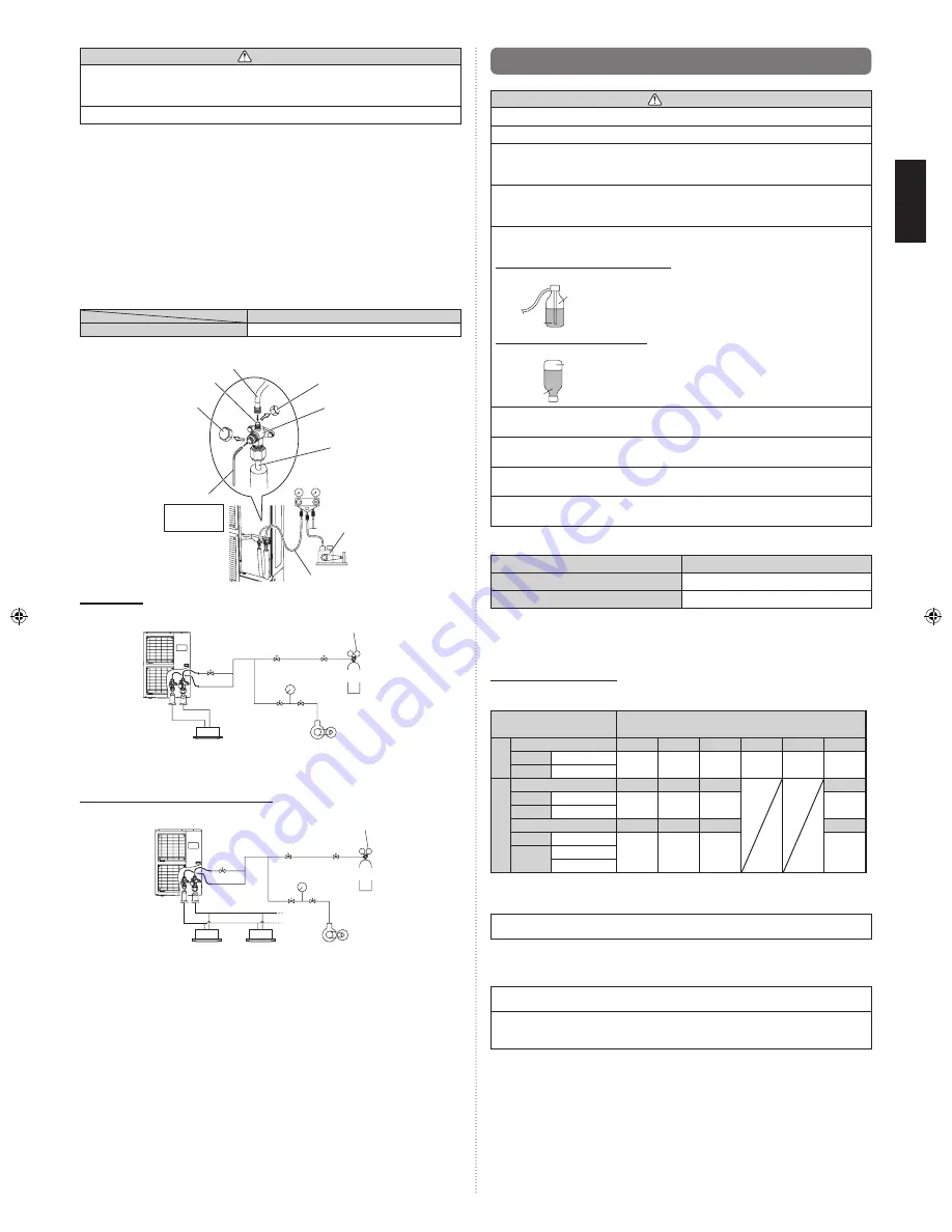
(1)   Check that the valves are closed by removing the blank caps from the gas and 

liquid pipes.

(2)   Remove the charging port cap, and connect the gauge manifold and the vacuum 

pump to the charging valve with the service hoses.

(3)  Vacuum the indoor unit and the connecting pipes until the pressure gauge indicates 

–0.1 MPa (–76 cmHg).

(4)   When –0.1 MPa (–76 cmHg) is reached, operate the vacuum pump for at least 


60 minutes.

(5)  Disconnect the service hoses and fit the charging port cap to the charging valve to 

the specified torque. (Refer to below table)

(6)  Remove the blank caps, and fully open the 3-way valves with a hexagon wrench 

[Torque: 6 to 7 N·m (60 to 70 kgf·cm)].

(7)   Tighten the blank caps of the 3-way valve to the specified torque. (Refer to Table A 

on page 8.)

Tightening torque [N·m (kgf·cm)] 

Charging port cap

10 to 12 (100 to 120)

Service hose

Service hose with valve core

Charging port

Blank cap

Hexagon wrench

Connecting pipe

Gauge manifold

Vacuum pump

Charging port cap

3-way valve

Use a 4 mm

hexagon 

wrench

Single type

Pressure regulating valve

Pressure gauge

Nitrogen

Indoor unit

Outdoor unit

Vacuum pump

Simultaneous operation multi type

Outdoor unit

Indoor unit

Indoor unit

Vacuum pump

Pressure gauge

Pressure regulating valve

Nitrogen

9379069274-04_IM.indb   9

28/11/2555   10:57:06

Summary of Contents for AOYG36LATT

Page 1: ...utorizado MANUALE DI INSTALLAZIONE UNITÀ ESTERNA tipo a 3 fasi A uso esclusivo del personale tecnico autorizzato ΕΓΧΕΙΡΙΔΙΟ ΕΓΚΑΤΑΣΤΑΣΗΣ ΕΞΩΤΕΡΙΚΗ ΜΟΝΑΔΑ Τριφασικού Τύπου Μόνο για εξουσιοδοτημένο τεχνικό προσωπικό MANUAL DE INSTALAÇÃO UNIDADE EXTERIOR Tipo trifásica Apenas para pessoal de assistência autorizado РУКОВОДСТВО ПО УСТАНОВКЕ ВНЕШНИЙ МОДУЛЬ 3 фазного типа Только для авторизованного обслу...

Page 2: ...ain the unit Do not place any other electrical products or household belongings under indoor unit or outdoor unit Dripping condensation from the unit might get them wet and may cause damage or malfunction of your property 2 ABOUT THE UNIT d 2 1 Precautions for using R410A refrigerant WARNING Do not introduce any substance other than the prescribed refrigerant into the refrigeration cycle If air en...

Page 3: ...rant pipe connections or other areas Touching the refrigerant directly can cause frostbite If a refrigerant leak occurs during operation immediately vacate the premises and thoroughly ventilate the area If the refrigerant comes in contact with a flame it produces a toxic gas The basic installation work procedures are the same as conventional refrigerant models However pay careful attention to the ...

Page 4: ...tion route installation space maintenance space and access and install the unit in a location with sufficient space for the refrigerant piping Observe the installation space specifications that are shown in the figures Keep the same space at rear air intake Provide the same space for the air intake at the rear of the outdoor unit If the installation is not performed according to the specifications...

Page 5: ...low If overturning prevention is required purchase the necessary commercially available items Bolt 20 mm Nut Base Fix securely with bolts on a solid block Use 4 sets of commercially available M10 bolt nut and washer 4 PIPE SELECTION 4 1 Selecting the pipe material CAUTION Do not use existing pipes Use pipes that have clean external and internal sides without any contamination which may cause troub...

Page 6: ...ference H1 Indoor unit to outdoor unit m 30 Max height difference H2 Indoor unit to indoor unit m 0 5 View Example L2 L3 L4 L1 H1 H2 1 For the standard pipe diameter 4 4 Connectable pipe diameter and max piping length The figures enclosed by a thick lined frame indicate the standard pipe diameter and max piping length 4 4 1 Single type installation Capacity Btu h class 36 000 45 000 54 000 Pipe di...

Page 7: ...erant piping branches Branch pipes are twin or triple type for concurrent operation and may be used for piping between the outdoor and indoor units Select a twin or triple type branch pipe and purchase it before starting the installation work Shorten the length of branch pipes from a branch to indoor unit as short as possible Maximum length within 20 m Branch pipes shall be connected by welding br...

Page 8: ...art of Blank cap is sealed for protection Fasten blank cap tightly after opening valves Table A Blank cap mm in Tightening torque N m kgf cm 6 35 1 4 20 to 25 200 to 250 9 52 3 8 20 to 25 200 to 250 12 70 1 2 25 to 30 250 to 300 15 88 5 8 30 to 35 300 to 350 19 05 3 4 35 to 40 350 to 400 Operating the valves Use a hexagon wrench size 4 mm Opening 1 Insert the hexagon wrench into the valve shaft an...

Page 9: ...s 19 05 3 4 15 m 25 m 35 m g m Liquid 12 70 1 2 None 1 000 g 2 000 g 100 g m Gas 15 88 5 8 19 05 3 4 1 Refer to View in the table of 4 3 1 Single type installation Simultaneous operation multi type Twin L1 L2 L3 2 Pre charge length Triple L1 L2 L3 L4 3 Pre charge length 2 Refer to View in the table of 4 3 2 Simultaneous operation multi type installation 3 Refer to View in the table of 4 3 2 Simult...

Page 10: ... power factor improvement condenser Instead of improving the power factor the condenser may overheat Be sure to perform the earthing grounding work Do not connect earthing grounding wires to a gas pipe water pipe lightning rod or earthing grounding wire for a telephone Connection to a gas pipe may cause a fire or explosion if gas leaks Connection to a water pipe is not an effective earthing ground...

Page 11: ...s are provided for wiring Fig A Knock out holes are provided 2 each in the same size in front lateral and rear sides Fig B Fig A Fig B Installation method of One touch bush Please fix the One touch bush accessory as shown in the figure below Front connection Lateral connection Rear connection One touch cable bush Accessories One touch cable bush Accessories One touch cable bush Accessories Pipe co...

Page 12: ...the wiring is complete s d 7 PIPE INSTALLATION 2 WARNING Install the insulated pipes so that they do not touch the compressor 7 1 Installing insulation Use an insulation on the refrigerant pipes to prevent condensation and dripping Fig A Determine the thickness of the insulation material by referring to Table A Table A Selection of insulation for using an insulation material with equal heat transm...

Page 13: ...EAK CUT L5 L6 L7 Orange Lights on during Peak cut function when local setting is activated Lighting pattern of L5 L6 and L7 indicates peak cut level _ Refer to 9 LOCAL SETTING Switch Function or operation method SW1 DIP switch For selecting cooling or heating during test operation Positions 2 to 4 of DIP switch are not used SW2 Push switch To switch between Local setting and Error code display SW3...

Page 14: ...AT Lower COOL ENTER TEST RUN switch 10 2 1 Operating procedures for the test run 1 Check the 3 way valves both at the liquid side and gas side are opened 2 Set the operation mode to COOL or HEAT POWER MODE ERROR TEST RUN PUMP DOWN LOW NOISE PEAK CUT L1 L2 L3 L4 L5 L6 L7 In the first test run be sure to set the operation mode to COOL The operation mode cannot be switched between COOL and HEAT durin...

Page 15: ... valves both at the liquid side and gas side are opened 2 Turn the power on POWER MODE ERROR TEST RUN PUMP DOWN LOW NOISE PEAK CUT L1 L2 L3 L4 L5 L6 L7 3 Press PUMP DOWN switch for 3 seconds or more after 3 minutes after power on ERROR TEST RUN PUMP DOWN LOW NOISE PEAK CUT POWER MODE L1 L2 L3 L4 L5 L6 L7 LED display lights on as shown in the above figure and the fans and the compressor start opera...

Page 16: ... 4 PFC AD detection error 2 6 4 PFC hardware error 2 6 5 IPM error Trip terminal L error 2 6 8 Rush current limiting resister temp rise protection 2 7 1 Discharge temp sensor error 2 7 2 Compressor temp sensor error 2 7 3 Heat Ex middle temp sensor error 2 7 3 Outdoor unit Heat Ex liquid temp sensor error 2 7 4 Outdoor temp sensor error 2 7 7 Heat sink temp sensor error 2 7 7 PFC heat sink temp se...

Page 17: ......

Reviews: