


3.2
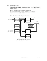
Circuit Configuration
This scanner uses CCD image sensor scanning system. This scanner consists of
following sections;
f
Optical system (including fluorescent lamp, and lenses)
f
Video circuit (including CCD sensor, amplifier, and A/D converter)
f
Scanner driver (including stepping motor and motor driver circuit)
f
Control circuit (MPU circuit)
f
Power section
Figure 3.2 is the function block diagram of this scanner.
Figure 3.2 Function block diagram
Motor driver
circuit
Power section
Control circuit
(MPU circuit)
Power switch
Image processing
circuit
¬
(option
)
Operator panel
Mechanism
section
Flatbed ADF
Controller
100 to 120 VAC
220 to 240 VAC
Video circuit
50FH5037E
>
02
3
$
3
Summary of Contents for 50FH5037E-02
Page 1: ...M3097E IMAGE SCANNER OEMMANUAL 50FH5037E 02 ...
Page 2: ...50FH5037E 02 i ...
Page 4: ...This page is intentionally left blank ii 50FH5037E 02 ...
Page 8: ...This page is intentionally left blank vi 50FH5037E 02 ...
Page 10: ...This page is intentionally left blank viii 50FH5037E 02 ...
Page 12: ...This page is intentionally left blank x 50FH5037E 02 ...
Page 14: ...Figure 1 1 M3097E outer view 1 2 50FH5037E 02 ...
Page 16: ...This page is intentionally left blank 1 4 50FH5037E 02 ...
Page 26: ...This page is intentionally left blank 2 10 50FH5037E 02 ...
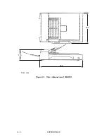
Page 28: ...Figure 3 1 Outer dimensions of M3097E 696 Unit mm 497 173 3 2 50FH5037E 02 ...
Page 38: ...This page is intentionally left blank 4 4 50FH5037E 02 ...
Page 50: ...This page is intentionally left blank 5 12 50FH5037E 02 ...
Page 136: ...This page is intentionally left blank B 2 50FH5037E 02 ...
Page 141: ......
Page 142: ......