background image

5

1F03 1781

1

  Checking mounting surface strength

The mounting surface should have sufficient 
strength enough to support the cooker hood.
Mount the cooker hood on a place durable to 
support the weight of the cooker hood.
[Weight: 21 kg (GFP-600), 23 kg (GFP-700), 26 
kg (GFP-900)

]

 In the case of boarded wall

 If the thickness is more than 20mm, mount 

the cooker hood directly to the wall.

 If the thickness is less than 20mm, embed 

a reinforcing board and mount the cooker 
hood to this board.

 In the case of a concrete/tile faced wall

 Embed a reinforcing board in the wall in 

advance, or use a carl plug or the like.

2

  Power supply plug

The power plug of this cooker hood is 5A 3-pin 
plug (BF Type: BS1363). 
Be sure to use the wall outlet only for the cooker 
hood.

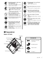
Checking accessory parts

Take out the main unit and accessory parts 
(screws, mounting brackets, etc.) from the 
packing box, and check whether there is any 
shortage.

5

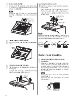
  Removing oil receiving cover

Grasp the oil receiving cover with one hand at 
each end. Pull the top of the cover out and down, 
and then lift the bottom of the cover to detach it 
from the body.

Note 

Place the range hood on the sheet etc. in order 
not to scratch the floor.

Catch

Oil recieving cover

6

  Removing rectifier panel

Loosen the rectifier panel screws attaching the 
rectifier panel, move the rectifier panel upward 
slightly to free rectifier panel screws from the 
rectifier panel mounting guide holes and the body 
catches.

Note

In order not to drop the rectifier panel, hold it 
by both hands securely. If dropped, it may be a 
cause of injury, flaw or warp of parts, etc.

Rectifier panel mounting guide hole

Rectifier panel screw

Rectifier panel

Catch

4

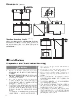
  Preparing exhaust duct

1) Referring to "Dimensions" on page 4, make a 

hole on the wall for exhaust duct.

2) Set 

150 stainless or spiral duct to the top of 

the cooker hood as shown, and perform finish 
work around it. (In case of the concrete, tile, 
and mud wall.)

30~50

(Unit: mm)

125

Center line

Summary of Contents for GFP-600

Page 1: ...ep this manual in a convenient place for future reference To the sales shop installer After installing please give this manual to the user without fail Safety Precautions 2 Preparation 3 4 Name of Parts 3 Dimensions 4 Installation 4 8 Preparation and Check before Mounting 4 6 Cooker Hood Mounting 6 7 Assembly 7 8 Operation Check 8 Installation Manual Cooker Hood 1F031781 ...

Page 2: ...dust accumulated on the blades of the power plug or on their roots wipe off well Fire may result in Don t spray water on the electric parts Fire or electric shock may result in When there may be a gas leak in your gas hob don t switch on or off the cooker hood Gas explosion may result in Wipe off dust Assembly cautioned Regulations concerning the discharge of air have to be fulfilled The air must ...

Page 3: ...ower plug hold the plug itself Don t pull the cord anyway The cord may be damaged and fire or electric shock may result in Assembly cautioned Contact prohibited Contact prohibited Be sure to wear gloves when care and maintenance Injury by the sharp edges or corners may result in Ensure that electric wiring is made safely according to the standard or regulations related Incorrect wiring may result ...

Page 4: ...cooking vessels on the hob and the bottom of the cooker hood When the cooker hood is located above a gas appliance this distance shall be at least 800mm If the instructions for installation for the gas hob specify a greater distance this has to be taken into account CAUTION 5 Use a gas range having a narrower width than that of the cooker hood 6 Avoid using the cooker hood with changes in the spec...

Page 5: ... check whether there is any shortage 5 Removing oil receiving cover Grasp the oil receiving cover with one hand at each end Pull the top of the cover out and down and then lift the bottom of the cover to detach it from the body Note Place the range hood on the sheet etc in order not to scratch the floor Catch Oil recieving cover 6 Removing rectifier panel Loosen the rectifier panel screws attachin...

Page 6: ... direction If it s installed incorrectly it may cause bad discharge abnormal noise etc Correct Wrong 7 Removing baffle filter Remove each filter screw fixing the baffle filters by turning in the counterclockwise direction and remove the baffle filters Note Be sure to hold the baffle filter with hand when removing it Otherwise it may drop and result in injury Baffle filter Filter screw Loosen Cooke...

Page 7: ...tape etc Assembly 2 Attaching baffle filters Align the baffle filter by placing the bottom of the baffle filter in the catches hold it in place with one hand and use the other hand to fasten each filter screw at the top firmly turn clockwise to fasten Catch Tighten Baffle filter Filter screw 1 Stripping off the fixing tape Strip off the oil tray fixing tape Fixing tape Oil tray 3 Attaching rectifi...

Page 8: ...ut a vent cap not supplied on the duct end outside as a rain cover Vent cap Not supplied Duct Catch Oil recieving cover 1 Power supply Connect the power plug to the wall outlet 220V 230V 240V AC 2 Operation check 1 Turn the alarm buzzer switch to the ON position Note Keep the alarm buzzer switch always in the ON position 2 While operating the cooker hood by pushing the applicable control switches ...

Reviews: