background image

RD-S45T

35

 -

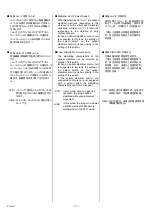
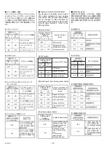
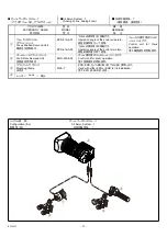
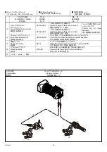
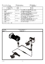
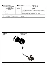
■ オールサーボシステム-3

(デジタルフォーカス、デジタルズーム)

All Servo System - 3

(Digital Focus, Digital Zoom)

■ 所有伺服系统-3

(数字聚焦、数字变焦)

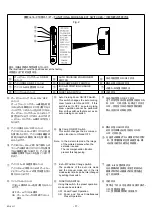
アクセサリ名称

ACCESSORY  NAME 

附件名称

型  名

MODEL 

型  号

備    考

REMARKS 

备    注

EPD-4A-E01 

つまみの操作角は1回転です。

Operation angle of the knob is one turn. 

旋钮的操作角为一个转角。

フォーカスポジション
デマンドユニット

Focus Position Demand Unit 

聚焦定位控制部件

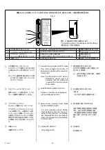
EPD-4A-E02 

つまみの操作角は2回転です。

Operation angle of the knob is two turn. 

旋钮的操作角为两个转角。

フォーカス操作用のコントロ
ールユニットです。

Control  unit  for  focus 

operation. 

用于聚焦操作的控制部件。

ズームレートデマンドユニット

Zoom Rate Demand Unit 

变焦遙控把手部件

ERD-10A-D01 

ズーム操作、プリセット操作用のコントロールユニットです。

Control unit for zoom operation and preset operation. 

用于变焦操作和预设操作的控制部件。

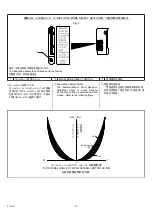
接続ケーブル

Connection Cable 

连接线

EBF-1 

レンズ

 - EPD

接続用のケーブルです。


Cable for electrical connection between lens and EPD. 

用于镜头和

 EPD 

之间电连接的电线。


マウンティングクランプ

Mounting Clamp 

安装夹

MCA-6B 

EPD

ERD

をパン棒に取り付けるときに使用します。


Used with EPD and ERD for their installation. 

用于

 EPD 

 ERD 

的安装。


レンズ  / 

Lens

  / 

镜头


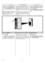
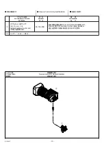
システム図

Configuration 

配置图

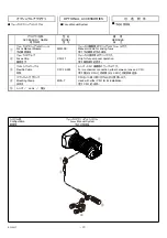
オールサーボシステム-3

All Servo System - 3 

所有伺服系统-3

Summary of Contents for FUJINON HA25x11.5BERD-S18D

Page 1: ...HA42 13 5BERD U48 5N BB00033243 102 LP428A U48 2804...

Page 2: ......

Page 3: ...ories is able to supply sufficient electric power to the lens system If not the lens system may not work normally and the camera may be damaged The specifications of the power consumption of the lens...

Page 4: ...let the lens adjust to the ambient temperature of the place where the lens will be used prior to using the lens Be sure not to subject the front part of the lens to any impact when operating the came...

Page 5: ...10 SJ T11364 GB T26572 GB T26572...

Page 6: ...tes that this product shall not be treated as household waste Instead it should be taken to an applicable collection point for the recycling of electrical and electronic equipment By ensuring this pro...

Page 7: ...n 12 5 Zoom Limit Operation 13 Preset Operation 16 1 Zoom Preset Operation 17 2 Zoom and Focus Simultaneous Preset Operation 18 Macro Operation 19 OpticalStabilizer 20 Other Functions 22 About Functio...

Page 8: ...amera attach the lens supporter mounted on a tripod Note Refer to the instruction manual of the lens supporter a b c d e a Take the rear lens cap off b Rotate the mount clamp ring on the camera fully...

Page 9: ...sm is carried out for about five seconds During the setting stabilizer ON OFF indicator refer to page 20 on the top of the drive unit blinks In this setting operation do not perform panning or tilting...

Page 10: ...nstalling the lens to a camera for the first time or installing it to another camera CONDITIONS OF OBJECT AND DIAPHRAGM 1 Object cut off the Siemens Star the chart made up of radial black and white li...

Page 11: ...osition d Operate the zoom to set it to the telephoto end e Operate the focus to bring the object into focus f Operate the zoom to set it to the wide end again and check that the optimum focus positio...

Page 12: ...ing causes the iris to move toward the closed side and counterclockwise rotation toward the open side Note 1 Although the iris operation mode is in Manual the iris is adjusted automatically while the...

Page 13: ...de to focus on an object on the near side The remote control operation is also available with optional accessories Set the focus servo manual select knob to S when using a servo control accessory S FO...

Page 14: ...ollowing five operation modes Page For the operating instruction in each mode refer to the description on each mode The remote control operation is also available with optional accessories While the p...

Page 15: ...b clockwise to increase the speed In quickzoom operation pressing a switch moves the zoom to the tele end quickly The operator can use this function in such occasions listed below When rapid zooming t...

Page 16: ...m movement restarts After this operation if the switch is released the zoom will move to its former position quickly Note 1 By setting an appropriate switch in the area of Function Mode Select Switche...

Page 17: ...g the zoom seesaw control lever press the quickzoom auto crusing zoom switch The auto cruising zoom function will work d Release your hand from the zoom seesaw control lever The zoom will move to the...

Page 18: ...tation of the zoom ring viewed from the camera side moves the zoom to the wide side and counterclockwise rotation to the tele side 2 3 4 a M b 3 1 Releasing There are three ways to release the auto cr...

Page 19: ...function can be used in the servo operation mode The setting of the zoom limit positions can be done in the manual operation mode By using this function the zoom movement toward both the tele side and...

Page 20: ...ide zoom limit position will be set Either side of the zoom limit positions can be set at first Note2 The wide side zoom limit position cannot be set beyond the tele side zoom limit position toward th...

Page 21: ...and the wide side zoom limit positions when the seesaw control lever is operated the zoom will move only toward the zoom limit positions not toward the opposite side of them Note2 If a zoom rate dema...

Page 22: ...or the operating instruction in each mode refer to the description on each mode 1 17 2 18 While the zoom limit function is being used these switches work as the zoom limit switches ZOOM SEESAW CONTROL...

Page 23: ...ermined position then stops During this operation the shot recalling speed can be changed by means of the zoom maximum speed control knob In this operation the zoom moves to a predetermined position b...

Page 24: ...Focus Position Demand Unit EPD 4A E01 EPD 4A E02 EPD 4A E01 or EPD 4A E02 EPD 4A E01 EPD 4A E02 S d a b Set the quickframe manual zoom select knob to ON d Set the focus servo manual select knob to S...

Page 25: ...ssible to shoot an object while the macro ring is in an intermediate position In this case the values of the M O D and the object area at M O D are those of between a normal and a closeup shot PROCEDU...

Page 26: ...cator illumninates and the optical stabilizer works In the OFF state the indicator goes out and the lens housed in the optical stabilizer is fixed at the center of the optical axis If an optical stabi...

Page 27: ...Stabilizer H V V Select Switch H V V In this mode even in a panning operation the image will be stabilized without an abnormal movement The stabilizing characteristic of the optical stabilizer can be...

Page 28: ...tches is properly arranged this switch works as a quickzoom switch or a quickzoom auto cruising zoom switch refer to page 24 Return Switch While pressing this switch the return video picture can be se...

Page 29: ...optional accessory S FUJINON TV ZOOM LENS D C 12V ZOOM FOCUS EXP STABI M ZO O M CONNECTOR FOR EXPANSION CONNECTOR FOR POWER SOURCE Connector for Power Source If sufficient power is not obtained from...

Page 30: ...uickzoom switch The function of the VTR switch incorporated in the zoom rate demand unit or the shot box linked to this lens is also changed to that of the quickzoom switch Return QuickZoom Select Swi...

Page 31: ...ITCH ON OFF ON OFF IRIS COMP ON OFF SWITCH ON OFF A M IRIS A M POSITION CHANGE SWITCH A M FUNCTION SWITCH Using this switch the preset operation mode can be selected OFF ON OFF Zoom Preset Operation O...

Page 32: ...his switch changes the function of serial communication with a camera to ON and OFF ON OFF ON OFF ON OFF ON OFF In a zoom operation with an analog zoom demand control unit the zoom mode function funct...

Page 33: ...om Seesaw Control Lever can be selected from ten modes Refer to the following figure 10 FUNCTION MODE SELECT SWITCHES Fig 4 The illustration shows the positions set at the factory ZOOM MODE SELECT SWI...

Page 34: ...ect Switches Function of QuickZoom Auto Cruising Zoom Switch ON ON Quickzoom auto cruising zoom switch OFF OFF Does not function ON OFF Quickzoom Switch OFF ON Auto cruising zoom switch Iris Mode Sele...

Page 35: ...elow The adjusting trimmer becomes visible inside the drive unit by removing the cap at the front of the drive unit Use a small screwdriver or similar implement to rotate the trimmer IRIS SENSITIVITY...

Page 36: ...detach it ATTACHING a Rotate the hood attaching knob counterclockwise to loosen it b Align the guide of the lens hood to the notch of the lens and insert the lens hood until the mating surfaces of the...

Page 37: ...together with desiccant into a vinyl bag for sealing to remove the moisture inside STORAGE If it is assumed that the lens will not be used for a long term store it in a place where high temperature m...

Page 38: ...dule FMM 3B Manual module for driving focus Focus Grip CFH 11 Grip for focus manual operation Flexible Cable CFC 12 990 CFH For mechanical connection either between lens and CFH CFH CZH Mounting Clamp...

Page 39: ...knob is one turn Focus Position Demand Unit EPD 21A A02 Operation angle of the knob is two turn Control unit for focus operation Zoom Rate Demand Unit ERD 20A A02 Control unit for zoom operation Mount...

Page 40: ...us Position Demand Unit EPD 21A A02 Operation angle of the knob is two turn Control unit for focus operation Zoom Rate Demand Unit ERD 10A D01 Control unit for zoom operation and preset operation Moun...

Page 41: ...E02 Operation angle of the knob is two turn Control unit for focus operation Zoom Rate Demand Unit ERD 10A D01 Control unit for zoom operation and preset operation Connection Cable EBF 1 EPD Cable fo...

Page 42: ...eration Zoom Rate Demand Unit ERD 10A D01 Control unit for zoom operation and preset operation Connection Cable EEC 13 ESB FSP Cable for electrical connection between ESB and lens FSP ESB EPD Conversi...

Page 43: ...Control by Personal Computer Configuration All Servo System 5 ACCESSORY NAME MODEL REMARKS EXTENSION CABLE SA 206A 005 Required when a personal computer is used to control the iris focus and zoom of t...

Page 44: ...rol for Optical Stabilizer Configuration Remote control for Optical Stabilizer ACCESSORY NAME MODEL REMARKS Optical Stabilizer Control Unit EA 12A 03B ON OFF Remote ON OFF controller for the optical s...

Page 45: ...End 1888 mm 1061 mm 45 mm 25 mm 944 mm 530 mm 22 mm 13 mm Front Clear Aperture of Lens Rear 115 5 mm 23 6 mm Filter Screw M127 0 75 Iris Control Servo or Manual Zoom Control Servo Focus Control Manua...

Page 46: ...MEMO...

Page 47: ...ILLUSTRATIONS...

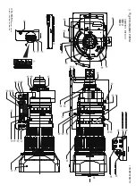
Page 48: ...M AUTO CRUISING ZOOM SWITCH MOUNT ZOOM SEESAW CONTROL LEVER HIGH STD STABI HIGH STD SELECT SWITCH HIGH STD RETURN SWITCH THREADED HOLE FOR LENS SUPPORTER VTR VTR SWITCH VTR CONNECTOR FOR EXPANSION ON...

Page 49: ...mm UNLESS OTHERWISE SPECIFIED UNIT mm mm OUTLINE DRAWING HA42x13 5BERD U48 GLP428AU480811...

Page 50: ......

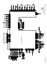
Page 51: ...AMP ASSY MAIN AMP ASSY MAIN AMP ASSY 2 WIRING DIAGRAM HA42x13 5BERD U48...

Page 52: ......

Page 53: ...SIEMENS STAR CUT LINE...

Page 54: ......

Page 55: ...Shanghai 200120 China TEL 86 21 5010 6000 FAX 86 21 5010 6750 http www fujifilm com cn products optical_devices FUJIFILM China Investment Co Ltd Beijing Branch Room 2606 No 1 Taikang financial Tower N...

Page 56: ......

Reviews: