

INSTALLATION POINTERS
:
:
:
:
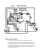
1.Please follow wiring connections strictly to wiring diagram provided.
2. In case of existing fan motor has only 2 speed,please connect PCB’s
【
HI
】
and
【
Med
】
wires together to fan motor’s
【
high-speed
】
wire connection.
3. Please check thoroughly all wiring connections to ensure correct connections
and voltage supply .Any wrong wiring will result in damaging PCB and
it shall not be warrantable.
WIRING DIAGRAM
AC
2
2
0
V
COMP
COMP
COMP
COMP
THERMISTOR
B
L
A
C
K
W
H
IT
E
TRANSFORMER
SECONDARY
COMPRESSOR
DC-FLAP
BLACK
INDOOR UNIT
FAN MOTOR
START CAP.
START CAP.
H8
H7
CN5
CN3
RECEIVER
BOX
ACN
ACL
H3
H2
DISP
TH
CN2
TR/OP
CN1
●
●
B
L
U
E
BROWN
YELLOW
TRANSFORMER
PRIMARY
COIL
COM
NO
L
N
EARTH
NF166
(SM450-12---1.2uF)
1
6-PIN:red wire put pin1
5-PIN:red wire put pin2
FLAP
LO
HI
ME
H9


