background image


– 5 – 


5


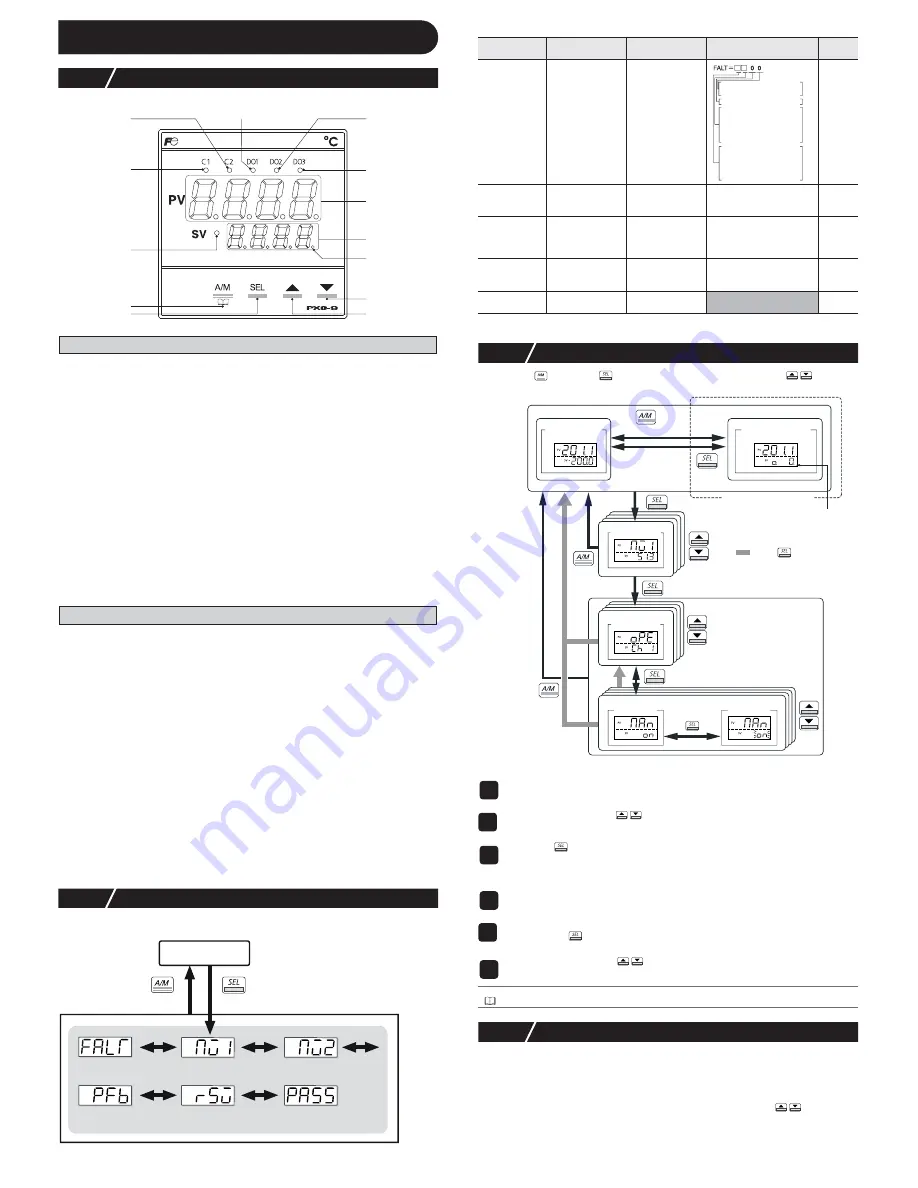
Display and Operations


5-1


Part names and functions


Operation Parts


USER Key


Pressing this key in monitoring mode display or setup mode display returns you to the PV/SV display.
Pressing this key on the PV/SV display allows you to set the function for "


UkEY


" under the system menu

("


SYS Ch 7


"). (The factory set function for this key is switching between auto and manual.)


SEL Key


Switches the PV/SV display to the monitoring mode display or setup mode display.


Switches to setup mode when parameter display, and this key functions as the select key when changing
parameters.
Holding this key down in channel display or parameter display returns you to the PV/SV display.


Pressing this key at PV/SV display in manual mode, manual output value is shown
in the lower display.


 Key

Pressing once will increase the setting value by one. Holding down the button will continue to
increase the value.
It changes SV on the PV/SV display.
It is also used to move between items in channel screen display and parameter screen display.

 Key

Pressing once will decrease the setting value by one. Holding down the button will continue to
decrease the value. It changes SV on the PV/SV display.
It is also used to move between items in channel screen display and parameter screen display.

Display

C1/C2 Lamp

Displays the condition of the control output. Lights ON at 100% output and goes out at 0% out-
put. For values between 0% and 100%, the output is indicated by the length of time the lamp
flickers.When acting as a valve control, the C1 lamp will light with OPEN output, and the C2
lamp will flickers with CLOSE output.

DO1/2/3 Lamp

Lights ON when there is digital output is on state (DO1, DO2, DO3).  The lamp flickers when
delay behavior is on.

PV Display

Displays the measurement value (PV). Displays the name of the parameter when setting
parameters.

SV Display

Displays the setting value (SV). Also can display the output value during manual mode. Dis-
plays the parameter setting value when setting parameters. Displays "

rEM

" during remote SV

operation, and "

SoFT

" and set value alternately during soft start.

SV Lamp

Lights when displaying the setting value (SV). Goes out when displaying the manual output
value.
The lamp flickers while performing ramp soak or lamp SV operations.

MAN/AT/SELF Lamp

Normally lights up during manual mode and blinks during auto-tuning or self-tuning.

5-2

Monitor Display and Status Display

In monitor mode, the PV display shows item names, while the SV display shows the 
input/output values.

For more details on “

PASS

” (PASS), see “5-6 Key Lock and Password” (page 6).

For more details on (Note) in the Remarks column, see “6 Parameter List” (page 6).

5-3

Basic Operations

Pressing the 

 key or the 

 key switches between modes. Pressing 

 in monitor

mode or setup mode allows you to choose menu items.

Changing SV (set values)

Changing MV (control output values)

5-4

Operations

For the following modes, the PV display will show the PV input value.

Operation Mode
SV display shows the SV setting value.

Manual Mode
An LED light decimal point lights ON in the lowest digit place in the SV display. An “o”
appears in the highest decimal place during MV display. Pressing the 

 keys sets the

MV (%).

DO1 Lamp

DO2 Lamp

DO3 Lamp

PV Display

SV Display

 Key

 Key

C2 Lamp

C1 Lamp

SV Lamp

USER Key

SEL Key

MAN/AT/SELF 

Lamp

PFB input value 
display (%)

RSV terminal 
input value display

Password entry

hold down

MV1 (%)

Error source 
display

MV2 (%)

monitor mode

operation mode

Parameter
display symbol

Parameter name

Function

Setting range

Remarks

"


FALT

"

(FALT)


Error source 
display

Displays the 
source of an error

"


Mv1


"  (Mv1)

MV1

Displays the output 
value of the control 
output (OUT1)

-3.0 to 103.0%

"


Mv2


" (Mv2)

MV2

Displays the output 
value of the control 
output (OUT2) 
(during dual control)

-3.0 to 103.0%

(Note4)

"


PFb


" (PFb)

Displays the PFB 
input value

Displays the input 
value of the 
position feedback

-3.0 to 103.0%

(Note8)

"


rSv


" (rSv)

RSV input value 
display

Displays the input 
value of the RSV

-5 to 105% FS (initial value)

(Note1)

1


Change the display to PV/SV display (shown when you turn on the power and
the SV lamp is lit).

2


Change the SV with the 

 keys.

3


Press the 

 key to save the values.


(The value will be automatically saved after 3 seconds even if a key is not pressed.)

1


Switch to manual mode.

2


Change the display to PV/MV display (MAN/AT/SELF lamp is lit).


(Pressing the


key in manual mode toggles between PV/SV display and PV/MV

display.)

3


Change the MV with the 

 keys.


(Changes are reflected to the MV as it is changed.)

Refer to


See “7-9 Manual Output” (page 12) for more about changing to manual mode.

fixed at 0

8bit : PV input underflow

9bit : PV input overflow

10bit: underrange

11bit: overrange

12bit: RSV underrange

13bit: RSV overrange

14bit: range setting error

15bit: EEPROM error

0bit: PFB input underflow

1bit: PFB input overflow

initial display

(PV/SV display)

observation

value display

channel menu

parameter

menu

parameter

setting

manual output

(PV/MV display)

hold down

(change 
    mode)

operation mode

monitor mode

manual mode

setup mode

hold down

hold down

hold down

only during manual mode

manual lamp ON

(change 
display only)

channel display

: Press        several times

parameter display

Summary of Contents for PXG5

Page 1: ...errors or failures may be caused Periodic maintenance is recommended for continuous and safe use of this equipment Some parts installed on this equipment have a limited life and or may deteriorate with age The warranty period for this unit including accessories is one year if the product is used properly 2 Caution 2 1 Cautions when Installing Please avoid installing in the following locations Loca...

Page 2: ... relay If the output operation frequency is high selecting a SSR SSC drive output type is recommended Proportionate cycles Relay output 30 seconds or more SSR SSC drive output 1 second or more When inductive loads such as magnetic opening closing equip ment etc as relay output equipment are connected use of Z trap manufactured by Fuji Electric Device Technology Co Ltd is recommended in order to pr...

Page 3: ...orque of about 0 8 N m Do not attach anything to unused terminals Do not use relay terminals PC loader interface PXG9 TOP TOP 13 24 37 48 61 72 49 60 1 12 25 36 waterproof packing panel terminal screw M3 96 96 79 5 10 2 91 5 115 5 MAX t 6 2 31 32 33 34 35 36 7 8 9 1 2 3 4 5 6 10 11 12 mounting fixture fastening torque 0 15 N m 25 26 27 28 29 30 Panel thickness 1 to 8 mm PC loader interface 25 36 1...

Page 4: ...ance bulb input 33 34 35 36 Current voltage input Voltage mV input 33 34 35 36 Measurement value input 29 30 29 30 RSV2 input CT2 input 25 26 27 28 DIO COM DI3 DI5 DI4 Digital input 25 26 27 28 DIO COM DI3 DI5 DI4 Digital input 25 26 27 28 29 30 DIO COM DI3 DI5 DI4 DO4 DO5 Digital input output 5 6 Power supply Note 3 Note 1 Note 2 50 60Hz 31 32 DI COM DI1 3 4 3 4 3 4 5 6 1 2 DI COM DI1 3 4 1 2 RS4...

Page 5: ...e SV display shows the input output values For more details on PASS PASS see 5 6 Key Lock and Password page 6 For more details on Note in the Remarks column see 6 Parameter List page 6 5 3 Basic Operations Pressing the key or the key switches between modes Pressing in monitor mode or setup mode allows you to choose menu items Changing SV set values Changing MV control output values 5 4 Operations ...

Page 6: ...channel and the authority of passwords 1 to 3 Note When FEFE FEFE is entered as PASS PASS all of the channels OPE ch to DSP ch can be displayed and set This super password function is useful when you forget the set passwords oPE ch PAS1 permissions PASS PAS1 PAS2 permissions PASS PAS2 PAS3 permissions PASS PAS3 Pid ch PLT ch PrG ch Mon ch SET ch SyS ch ALM ch CoM ch PFb ch PAS ch dSP ch Password l...

Page 7: ... Sets the integration time 0 to 3200 sec 240 sec d7 d7 Differential time 7 Sets the differential time 0 0 to 999 9 sec 60 0 sec hyS7 hyS7 ON OFF control hysteresis 7 Sets the hysteresis when using the ON OFF control 0 to 50 FS 1 C oL7 CoL7 Cooling proportional band 7 Sets the cooling proportional band 0 0 to 100 0 1 0 Note4 Parameter display symbol Parameter name Function Setting range Initial val...

Page 8: ...SV input filter Sets the time constant for the RSV input filter 0 0 to 120 0 sec 0 0 sec Note1 fixed at 0 8bit PV input underflow 9bit PV input overflow 10bit underrange 11bit overrange 12bit RSV underrange 13bit RSV overrange 14bit range setting error 15bit EEPROM error 0bit PFB input underflow 1bit PFB input overflow RST RST RST RST 1r C1r OUT1 range Sets the range of the control output OUT1 0 5...

Page 9: ...r alarm function bit2 non excitation output alarm function bit3 hold reset function RST PrCS PrCS Control target Allows you to select the control target SRV1 Servo control 1 SRV2 Servo control 2 PFB Position feedback control PFb Srv1 with PFB without PFB Note16 Stmd STMd Start mode Sets the operation mode when starting up Auto auto mode startup Man manual mode startup Rem remote mode startup STby ...

Page 10: ...ou will need to run auto tuning to set the PID parameter when using fuzzy control Setting fuzzy PID control Display Parameter name Function Setting range Initial value Remarks PAS1 PAS1 Password1 setup Sets password 1 0000 to FFFF 0000 PAS2 PAS2 Password2 setup Sets password 2 0000 to FFFF 0000 PAS3 PAS3 Password3 setup Sets password 3 0000 to FFFF 0000 Display Parameter name Function Setting rang...

Page 11: ...re changing back to self tuning 1 Display the system menu SYS Ch 7 2 Display the control parameter CTrL and choose PID2 Pid2 3 Press the key to set the value dead time t process value tuning SV lag time suppress overshoot ON OFF control equipment power t SV process value control loop close close open PV At set value Behavior Function oFF Stop Finish Stops or finishes auto tuning on Normal type The...

Page 12: ...et CAL to 3 in step 3 above This setting will automatically open and close the valve to adjust it auto matically Caution To manually adjust the valve carry out step 1 through step 7 as written above If the valve is not connected or connected incorrectly it can still be adjusted but will not achieve accurate results There is no open circuit judgment function for the valve opening feed back signal C...

Page 13: ...SV 1 2nd ramp 3rd ramp 4th ramp SV 2 SV 3 SV 4 Dis play Function Name Behavior ON OFF Judgment conditio n 0 No function Nothing happen 1 Switchover between standby ON OFF Switches between standby on and off Standby Standby Cancel Edge 2 Switchover between auto manual Switches between auto and manual control output Manual Auto Edge 3 Switchover between local remote Switches between local and remote...

Page 14: ...ting DO1 to DO5 Function Wire burnout circuit alarm 41 Loop break alarm 1 44 Heater burnout alarm 1 Wire break short circuit alarm 47 Load short circuit alarm Dis play Function Name Behavior ON OFF Judgment conditio n Settings complete Using them as alarms 1 to 31 Using them as events 35 to 102 or timers 32 to 34 1 Setting the System Menu 2 Setting the Alarm Menu 3 Setting the alarm menu page 14 D...

Page 15: ...2 Display hysteresis 1 A1hY and set the hysteresis 3 Display delay time 1 dLY1 and set the delay 4 Display delay time units 1 dL1U and set the units to minutes or seconds 5 Set the values for alarm 2 to alarm 5 as necessary 6 Press the key to set the value 1 Display the operation menu oPE Ch1 2 Set the alarm 1 set value AL1 or AL1L and AL1H The parameters displayed will vary according to the type ...

Page 16: ...time SFTM and set the time 4 Press the key to set the value 5 Turn off the power once and then re start the controller to begin soft start When the soft start function is turned on the lower display will alternate show ing SoFT and SV Note Do not use auto tuning at the same time 1 Display the setup menu SET h 6 2 Display FALT output 1 set value FLo1 and set the output value For dual control set FL...

Page 17: ...alue 1 Display the operation menu oPE Ch1 2 Display the selected PID number PLn1 and choose the PID No 3 Press the key to set the value 1 Display the palette menu PLT Ch 3 2 Display max selected PID number PL1M and set the PID number by choosing it with the user key 3 Display the user key function setting UKEy and set it to PID selection function 4 On the PV SV display pressing the user key will s...

Page 18: ... 7 and STbY is ON Normal control The controller does not have to be restarted Parameters may not be displayed q Check the settings of dP01 to dP30 w Check the password function Normal control The controller does not have to be restarted Input type Measurement range C Measurement range F Smallest input increment C Input code Resistance bulb JIS IEC Pt 100Ω 0 to 150 32 to 302 0 1 1 0 to 300 32 to 57...

Page 19: ...thout hold alarm may turn ON when starting up Caution When alarm action code is changed alarm set value may also become dif ferent from previous settings When alarm action type code is changed turn off the power once and then re start the controller before starting control Aln AL1 to AL5 show the alarm set values ALnh AL1h to AL5h show the alarm set values ALnL AL1L to AL5L show the alarm set valu...

Page 20: ... mV input voltage input current input 0 3 FS 1digit Indication resolution 0 3 FS or less Digital Output Relay contact output DO1 to DO3 1a contact 220V AC 30V DC 3A resistance load Transistor Output DO4 DO5 Open collector 30V DC 100mA max 2 contacts Judged ON 1V DC or less Digital input Contact or Transistor type Max 5 inputs 30V DC 3mA 1 input Judged ON 1kΩ or less contact or 5V DC or less transi...

Reviews: