Fuji Electric MICREX-SX series SPF User Manual Download Page 29

2-22

Section 2  Specifications

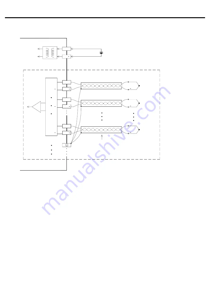
2-4-3  Thermocouple input (target type: NA0AX06-TC)

Multiplexer

J(K) extension cable


+


+

+

+24V DC

24V

24V+

TC5+

TC5

+

TC1

TC1+

+

TC0+

TC0

+

NA0AX06-TC

External power supply

Thermocouple

sensor

Thermocouple

sensor

Thermocouple

sensor

Summary of Contents for MICREX-SX series SPF

Page 1: ...series USER S MANUAL Analog Unit FEH527...

Page 2: ...EX SX series SPF User s Manual Instructions Standard MICREX SX series SPF FEH524 Describes the memory specifications and instructions specific to SPF series User s Manual Instructions Standard MICREX...

Page 3: ...terminals and exposed metal portion while the power is turned ON It may result in an electric shock to the operator Turn OFF the power before mounting dismounting wiring maintaining or checking otherw...

Page 4: ...in a correct orientation otherwise an erratic operation might occur Before touching the PLC discharge any static electricity that may have been collected on your body To discharge it touch a grounded...

Page 5: ...Revision The manual No is printed at the bottom right of the cover of this manual Printed on Manual No Revision contents Jan 2017 FEH527 First edition...

Page 6: ...input unit Type NA0AX06 MR 2 12 2 3 2 Analog output unit Type NA0AY02 MR 2 14 2 3 3 Analog input output unit Type NA0AW06 MR 2 16 2 3 4 Thermocouple input unit Type NA0AX06 TC 2 19 2 4 Wiring 2 20 2...

Page 7: ...3 PORT0 Y5 C4 C6 0 4 8 2 I 6 5 9 Y8 Y7 Y9 3 7 IN X X8 X0 24V OUT S S RX TX RUN ERR I2 I3 POW X4 X2 X1 X3 0 8 4 2 I I0 9 6 5 X6 X5 X7 X12 3 II 7 X10 X9 X11 X13 SINK SRCE max 400mA IN Max 3 units Basic...

Page 8: ...Hz 10V m 1 4 to 2 0 GHz 3V m 2 0 to 2 7 GHz 1V m IEC 61000 4 3 EFT B Electrical fast transient burst Equipment power I 0 power AC I O unshielded 2kV Data communication digital and analog I O s except...

Page 9: ...program loader Overall accuracy 1 Digital output value 12 bits 0 to 4000 2000 to 2000 14 bits 0 to 16000 8000 to 8000 Sampling period Synchronized with the scan of the basic unit Moving average 1 to 1...

Page 10: ...accuracy 1 Data type of digital input value INT type Output period Synchronized with the scan of the basic unit External wire connections 8 pole terminal block M3 x 2 Tightening torque 0 59 to 0 78 N...

Page 11: ...er No of output channels 2 channels External load resistance Voltage output 500 W to 1 MW Current output 0 to 500 W or less Analog output range 10 to 10V 5 to 5V 0 to 10V 0 to 5V 20 to 20mA 10 to 10mA...

Page 12: ...3092 0 F Cold junction automatic compensator Built in the unit Data type of digital output value INT type Sampling period 2 seconds high speed or 4 seconds low speed Collectively set for all channels...

Page 13: ...the resolution 3 0 to 10V 0 to 20mA when set at UNIPOLAR 2 0 to 5V 0 to 10mA when set at BIPOLAR 8191 2047 8000 2000 0 5V 10mA 0V 0mA 8000 2000 8192 2048 Digital otuput value INT type Analog input vo...

Page 14: ...alues in are the digital output values when 12 bits is selected for the resolution 4095 16383 4000 16000 0 5V 10mA 5V 10mA Digital output value INT type Analog input voltage current The values in are...

Page 15: ...A Digital output value INT type Analog input voltage current The values in are the digital output values when 12 bits is selected for the resolution 8191 2047 8000 2000 8000 2000 0 10V 20mA 10V 20mA 8...

Page 16: ...og output voltage current Digital input value INT type 3 0 to 10V 0 to 20mA when set at UNIPOLAR 2 0 to 5V 0 to 10mA when set at BIPOLAR 8191 8000 5V 10mA 0V 0mA 8000 8192 Analog output voltage curren...

Page 17: ...5V 10 to 10mA when set at BIPOLAR 8191 8000 10V 20mA 0V 0mA 8000 8192 Analog output voltage current Digital input value INT type 8191 8000 5V 10mA 5V 10mA 8000 8192 Analog output voltage current Digit...

Page 18: ...n set at UNIPOLAR 8 10 to 10V 20 to 20mA when set at BIPOLAR 8191 8000 10V 20mA 10V 20mA 8000 8192 Analog output voltage current Digital input value INT type 8191 8000 0 10V 20mA 10V 20mA 8000 8192 An...

Page 19: ...lue range Therefore remove the upper cover and control board when setting the jumper pin Pin layout of control board When the upper cover is removed Pin layout of I O board When the control board is r...

Page 20: ...nt 2 Functions 1 Status indication LED 2 Terminal block These are terminals for 24V DC power supply to operate the analog unit and analog input signal 3 JP1 Digital value range selection This jumper p...

Page 21: ...g signal range and digital value range Therefore remove the upper cover and control board when setting the jumper pin NA0AY02 MR 3 JP1 5 JPA CH1 5 JPA CH0 4 JPB CH0 4 JPB CH1 2 Terminal block 1 Status...

Page 22: ...analog input signal For the wiring method refer to 2 4 Wiring Digital value range JP1 setting 8192 to 8191 0 to 16383 Signal range JPA setting JPB setting 0 to 10V 10 to 10V 0 to 5V 5 to 5V 0 to 20mA...

Page 23: ...r cover and control board when setting the jumper pin NA0AW06 MR 3 JP1 JP1 D A A D B U B U B U 10V 5V I V CH0 CH1 4 JPA 6 JP3 6 JP4 U B 5V 10V I V CH0 CH1 5 JPB 7 JP5 CH0 to JP8 CH3 10V 5V B U 2 Termi...

Page 24: ...4 Wiring Digital value range JP1 setting 8192 to 8191 0 to 16383 3 JP1 Digital value range selection This jumper pin is used to set the digital value range for analog output upper side and analog inp...

Page 25: ...to 10V or 20 to 20mA 5 to 5V or 10 to 10mA 6 JP3 and JP4 Analog input range selection U B 5V 10V U B 5V 10V U B 5V 10V U B 5V 10V Voltage current Setting of JP5 CH0 to JP8 CH3 Voltage Current 7 JP5 to...

Page 26: ...pansion connector OUT 2 Terminal block Status indication LED Status Specification PWR of thermocouple input unit ON red While 5V DC power is normally supplied 2 Functions 1 Status indication LED 2 Ter...

Page 27: ...I1 V I I0 I0 15V 15V 24V 24V CH5 Input Voltage sou V External power supply 24V DC CH1 Input Current sou I CH0 Input Voltage sou V CH0 Example of voltage input CH1 CH5 NA0AX06 MR NA0AW06 MR Shielded tw...

Page 28: ...MR and NA0W06 MR V O1 I O1 AG I FG I I 15V 15V 24V O0 V O0 24V FG 24V DC V V NA0AY02 MR NA0AW06 MR External power supply Voltage input Current input Output CH0 Example of voltage output CH1 Example of...

Page 29: ...ications 2 4 3 Thermocouple input target type NA0AX06 TC Multiplexer J K extension cable 24V DC 24V 24V TC5 TC5 TC1 TC1 TC0 TC0 NA0AX06 TC External power supply Thermocouple sensor Thermocouple sensor...

Page 30: ...ifications 2 5 Dimensions NA0AX06 MR Analog input 6CH NA0AY02 MR Analog output 6CH NA0AW06 MR Analog input 4CH Analog output 2CH and NA0AX06 TC Thermocouple input 6CH have the same dimensions 80 Unit...

Page 31: ...e INT type WYo 5 Channel 5 Digital output value INT type WXo 0 Channel 0 Digital output value INT type WXo 1 Channel 1 Digital output value INT type WXo 2 Channel 2 Digital output value INT type WXo 3...

Page 32: ...4V OUT S S RX TX RUN ERR I2 I3 POW X4 X2 X1 X3 0 8 4 2 I I0 9 6 5 X6 X5 X7 X12 3 II 7 X10 X9 X11 X13 SINK SRCE max 400mA IN NA0AX06 MR Basic unit How to register units 1 Open the system definition scr...

Page 33: ...nit Target type NA0AX06 MR NA0AW06 MR How to set parameters 1 Right click the analog unit registered in the system definition screen and left click Properties The Module properties dialog box opens 2...

Page 34: ...0 C S 0 to 1700 C Moving average No moving average 2 4 or 8 times Sampling period High speed 2 seconds or low speed 4 seconds Unit Celsius or Fahrenheit How to set parameters 1 Right click the thermoc...

Page 35: ...Osaki 1 chome Shinagawa ku Tokyo 141 0032 Japan E mail micrex sx fujielectric com URL http www fujielectric com Materials covered in this document are subject to revision due to the modification of t...

Reviews: