


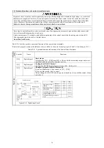


Table 2.2-4 Symbols, Names and Functions of the Control Circuit Terminals (Continued)
Cla
ssifi-
cation
Symbol Name
Functions
Alarm content
Provides the operation status of the protection function by 3bit terminals [Y2] to[Y4].
Refer to the chapter 4 for the relation between terminals and the protection feature.
(Transistor output circuit specification)
[Y2]
Transistor
output 2
[Y3]
15
Photocoupler
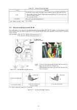
<Control circuit>
[Y1]
to
[Y4]
[CMY]
31 to 35 V
Vo
lta
g
e
Current
Figure 2.2-5 Transistor Output Circuit
Item Max.
ON level
2 V
Operation
voltage
OFF level
27 V
Maximum current at ON
50 mA
Leakage current at OFF
0.1 mA
[Y4]
Transistor
output 3
Transistor
output 4
- When a transistor output drives a control relay, connect a surge-absorbing
diode across relay’s coil terminals.
- When any equipment or device connected to the transistor output needs to be
supplied with DC power, feed the power (+24 VDC: allowable range: +22 to
+27 VDC, 100 mA max.) through the [PLC] terminal. Short-circuit between
the terminals [CMY] and [CM] in this case.
[CMY] Transistor
output
common
Common terminal for transistor output signals
Electrically isolated from terminals [CM].
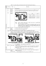
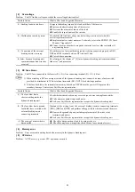
Connecting programmable logic controller (PLC) to terminal [Y2], [Y3] or [Y4]
Figure 2.2-6 shows two examples of circuit connection between the transistor output of the dynamic
braking unit’s control circuit and a PLC. In example (a), the input circuit of the PLC serves as a SINK for
the control circuit output, whereas in example (b), it serves as a SOURCE for the output.
C0
+2
4 V
D
C
Programmable
logic controller
SINK input
Photocoupler
<Control circuit>
[Y1]
to
[Y4]
[CMY]
31 to
35 V
Current
C0
Programmable
logic controller
SOURCE input
+24 VD
C
Photocoupler
<Control circuit>
[Y1]
to
[Y4]
[CMY]
31 to
35 V
Current
(a) PLC serving as SINK
(b) PLC serving as SOURCE
T
ransistor
outpu
t
Figure 2.2-6 Connecting PLC to Control Circuit
[Y5A/C] Relay
output
Ready to run
Turns ON when the dynamic braking unit is ready for the operation, for example, the
power supply to the main and the control circuits are established or the protective
function is not active.
Contact rating: 250 VAC 0.3 A, cos
= 0.3, 48 VDC, 0.5 A
Relay
output
[30A/B/C] Alarm relay
output
(for any error)
Outputs a contact signal (relay contact, 1C) when the protective function stops the
dynamic braking unit.
Contact rating: 250 VAC, 0.3 A, cos
= 0.3, 48 VDC, 0.5 A
Summary of Contents for BUC S-69D
Page 8: ......


