background image


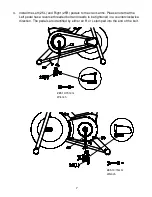
2.  Insert Handlebar Post(4) into Main Frame (1). Next insert Locking Knob(19) into Main 

Frame (1) and make sure that Front Column is through the Handlebar Post(4) before 
securing and tightening.   


3.    Install the handlebars(6) onto the Handlebar Post (4), with the three of 5/16" x 5/8” 

Socket Head Cap Bolt (88) and three of 5/16" × 1.5T_Spring Washer (49) by using the 
Combination M6 Allen Wrench & Phillips Head Screw Driver (86). 

#88. Socket Head   
Cap Bolt (3pcs) 


#86. M6_Combination M6 
Allen Wrench & Phillips 
Head Screw Drive 

#49. Split   
Washer(3pcs) 


Summary of Contents for FUE0009

Page 1: ...PLEASE CAREFULLY READ THIS ENTIRE MANUAL BEFORE OPERATING YOUR SPIN BIKE OWNER S MANUAL SPIN BIKE FUE0009...

Page 2: ...hand Do not touch any driving mechanism while it is in motion as possible injury could occur 6 In a home setting keep children away from the bike when it is not in use Keep children and pets away from...

Page 3: ...ent while exercising 4 Overweight or severely de conditioned individuals should be particularly cautious when using the equipment for the first time Even thought such individuals may not have historie...

Page 4: ...seat is in the desired position tighten the locking knob to secure the seat post 7 Note the final position mark on the seat post for future reference Seat Forward Aft Adjustment 1 Sit on bike with cra...

Page 5: ...resistance counterclockwise for less resistance 2 To apply the brake press down on the tension knob 3 Before dismounting apply the brake to stop flywheel or increase resistance and let flywheel come...

Page 6: ...olts 81 four 3 8 curved washers 83 and four 3 8 cap nuts 82 by using the 14 15mm Wrench 85 Assembly Instructions 82 Cap Nut 4 pcs 83 Flat Washer 4pcs 85 14 15m m Wrench 81 Carriage Bolt 4pcs Assembly...

Page 7: ...efore securing and tightening 3 Install the handlebars 6 onto the Handlebar Post 4 with the three of 5 16 x 5 8 Socket Head Cap Bolt 88 and three of 5 16 1 5T_Spring Washer 49 by using the Combination...

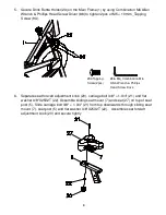
Page 8: ...the crank arms Please note that the Left pedal has a reverse threaded bolt and needs to be tightened in a counterclockwise direction The pedals are identified by either an R or L stamped into the end...

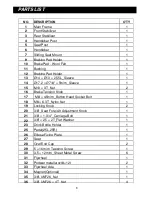
Page 9: ...ent knob 20 carriage bolt 3 8 1 3 4 21 and flat washer 3 8 X25X2T 22 Assemble sliding seat mount 7 and seat 27 on top of seat post 5 Slide carriage bolt 3 8 1 3 4 21 from top downwards through sliding...

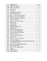
Page 10: ...t 2 16 Brake Tension Knob 1 17 M8 45m m_Button Head Socket Bolt 1 18 M8 6 3T_Nyloc Nut 1 19 Locking Knob 2 20 3 8 _Seat Fore Aft Adjustment Knob 1 21 3 8 1 3 4 _Carriage Bolt 1 22 3 8 25 2T_Flat Washe...

Page 11: ...60 Side Case R 1 61 Side Case L 1 62 Spacer for Stopper Axle 1 66 6203_Bearing 2 69 M6 45L_Idle Wheel Screw 2 73 25 5 16_Star Washer 1 76 Console Assembly Optional 1 80 M8 25L_Screws 2 81 3 8 2 1 2 _...

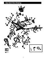
Page 12: ...11 Exploded View Drawing...

Page 13: ...2 7010 For efficient processing of your enquiry please have relevant date of purchase retailer name you purchased the item from and the brand on the product This warranty does not extend to any damage...

Page 14: ...modify any such rights or remedies that are implied by law Our goods come with guarantees that cannot be excluded under the Australian Consumer Law You are entitled to a replacement or refund for a m...

Page 15: ...itness to comply with a consumer guarantee under the Australian Consumer Law 3 The product was damaged through abnormal use no refund or repair can be offered The sending of replacements spare parts o...

Reviews: