Temperature and Humidity Sensor
Page 7/15
700-THS3 Rev. 6 -05 May 2015
3.
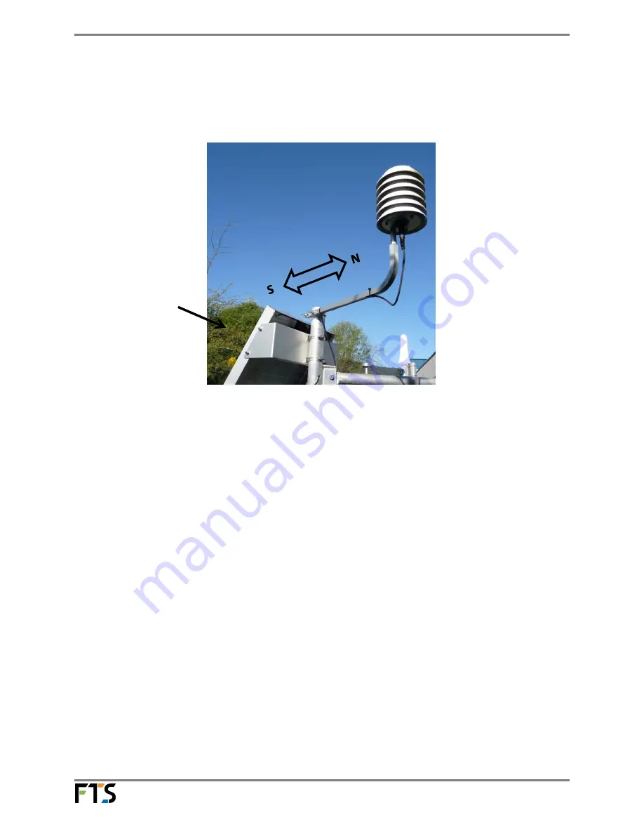
In the northern hemisphere, position the support arm so that the sensor is positioned south
of the mast and on the north side of the solar panel to ensure neither pieces of equipment
will be shaded. In the southern hemisphere, the positioning will be opposite.
Figure 2-3: Support arm positioning (northern hemisphere)
(Note: support arm may not appear exactly as shown)
4.
Attach the sensor cable to the support arm and the mast using cable ties.
5.
Connect the sensor cable to the data logger’s Temperature / Humidity connector (red ring).
NOTE: Key Installation Points:
a)
The sensor should be in the open, in a shade free area to ensure
accurate temperature readings.
b)
The sensor should be well away from external sources of heat (i.e. any
equipment at the site that might generate heat).
c)
The sensor should be given a minimum of thirty minutes to acclimatize
to a site after installation before data is taken.
2.3
Maintenance
FTS recommends that the sensor be returned to FTS for a yearly check of the THS-3 sensor’s
calibration.
Also, FTS recommends that during any site visit a visual check of the THS-3 cable, connector and
sensor filter is performed. Any observable damage should be noted so that the appropriate repairs
can be performed. The THS-3 sensor filter (FTS part number: 03-THS3-6192) is field replaceable in the
event that the sensor filter is clogged.
Please contact FTS technical support if the unit ceases to operate properly.
Solar Panel


