background image

Temperature and Humidity Sensor 


Page 10/15 

700-THS3    Rev. 6 -05 May 2015  

4)


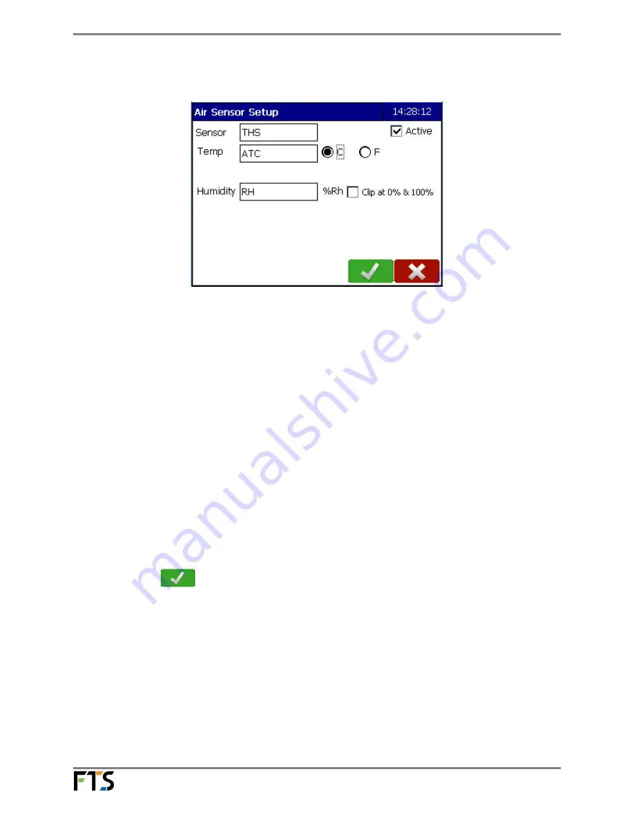
The Air Sensor Setup screen will be displayed:  


Figure 3-3:   

 
5)


Edit the fields by pressing on the field box: 


Sensor:


The default name for the sensor is THS.  You can change this if desired. 

Active: 


This box must be checked in order for the sensor to collect data 

Temp: 


This is the air temperature.  The default name is ATC.   You can change  


this if desired.  The default units of measurement is Celsius (C).  To  


change to degrees Fahrenheit, select the (F) radial button.     

Humidity:


This is the relative humidity.   

Clip at 0% & 100%: 

If checked, causes the datalogger to limit humidity values read from 
the sensor to the range of 0 to 100%. That is, any air sensor humidity 
measurements above 100% are reported as 100% and any 
measurements less than 0%  are reported as 0%.  


If the Clip at 0% & 100% is not enabled and the sensor reads outside of  


its range (higher than 117%) then an error (ERR) will be reported. 


6)


Select OK 

.   

 
i) 

If In-line Logging is enabled (from Station<Advanced<Edit<In-line Logging) the In 


Line Logging screen will be displayed.  Go to Section 3.2; 

 
ii) 

If In-line Logging is not enabled, you will be returned to the Sensors screen.  Go 


to Section 3.3. 


Summary of Contents for THS-3

Page 1: ...1 800 548 4264 www ftsenvironmental com 700 THS3 Rev 6 05 May 2015 THS 3 Temperature and Humidity Sensor Installation and Quick Setup Guide...

Page 2: ...ental com 700 THS3 Rev 6 05 May 2015 Contact information FTS 1065 Henry Eng Place Victoria B C V9B 6B2 CANADA www ftsenvironmental com Toll free 1 800 548 4264 Local 250 478 5561 Technical support htt...

Page 3: ...1 General Description 3 1 2 Specifications 4 Chapter 2 Installation and Maintenance 5 2 1 General 5 2 2 Tower Mounting 5 2 3 Maintenance 7 Chapter 3 Sensor Quick Setup Guide 9 3 1 Configuring the THS...

Page 4: ...humidity 0 to 1 Vdc equals 0 to 100 RH on the sensor connector The T H sensor assembly see Figure 1 1 houses the sensors and associated electronics Both sensors are protected from air borne contamina...

Page 5: ...und Power Humidity Output K Temperature Ground thermistor others No Connect Table 1 THS Sensor Signal Connections 1 2 Specifications The specifications for the THS 3 Temperature and Humidity Sensor ar...

Page 6: ...eight Correct installation height is dependent on regulations for the jurisdiction in which the equipment is to be deployed Ensure you review local regulations prior to installation In the United Stat...

Page 7: ...2015 Figure 2 1 Attaching the assembly to the support arm 2 Loosely attach the support arm to the mast or tower with the clamp bolts at the desired sensor height Ensure the support arm s V is fitted t...

Page 8: ...n the open in a shade free area to ensure accurate temperature readings b The sensor should be well away from external sources of heat i e any equipment at the site that might generate heat c The sens...

Page 9: ...en key to remove the three bolts securing the base of the sensor to the base plate of the housing assembly Figure 2 4 Sensor base showing bolts c Gently remove the sensor and inspect the filter for cl...

Page 10: ...ce NOTE After installation the sensor should be given a minimum of thirty minutes to acclimatize to a site before data is taken 3 1 Configuring the THS 3 1 Connect the THS 3 to the data logger on the...

Page 11: ...t select the F radial button Humidity This is the relative humidity Clip at 0 100 If checked causes the datalogger to limit humidity values read from the sensor to the range of 0 to 100 That is any ai...

Page 12: ...Line Logging does not have the full functionality as setting up Logging through the Data screen 1 Select the Edit button then Input the desired the Logging Interval press on the hour minute or second...

Page 13: ...bed here are displayed in blue Logging intervals created using the In line Logging feature are displayed in green Figure 3 6 Logging Intervals 3 Press the Add icon then the Edit icon Set the desired l...

Page 14: ...he Home page 3 4 Confirm Sensor Operation Now that the THS 3 is setup confirm its operation and ensure data is being logged 1 From the Home page select the Data icon to display the Data Status screen...

Page 15: ...turn to the Home page 3 5 Changing the Setup If you want to change the setup from the Home page select the blue Sensors icon then select the THS icon Select the Set up Cog which will bring you to the...

Page 16: ...vision Date Description 1 27 Jul 2006 Original release 2 2 Oct 2006 Updated specifications 3 25 Jan 2007 Added special order specification 4 11 Oct 2007 Updated for new filter updated specifications 5...

Reviews: