Page 20 of 26
Rev. A
10
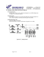
Displays, Audio Alarm and Control Button
10.1 Control button
ON/ OFF Button: Push it to turn on UPS, and push again to turn off UPS. (Please refer
to Chapter 3 for cold start & AC start)
10.2 Audio alarm
The buzzer is controlled by pin16 of CPU. When CPU sends a HI signal to buzzer from
pin16, buzzer is beeping. And CPU sends LOW signal to stop buzzer.
10.3 Display ( Figure S- 8)
There are 3 LEDs on front panel.
While control button is turned on, CPU sends a HI signal to turn on LED.
Figure S-8
Display Circuit
Summary of Contents for EP450 series
Page 2: ...Page 1 of 26 Rev A UNINTERRUPTIBLE POWER SYSTEM SPECIFICATION EP450 650 850 Series ...
Page 9: ...Page 8 of 26 Rev A Figure S 2 Control Power Circuit CH1 C15 å GND Figure W 1 Cold Start ...
Page 11: ...Page 10 of 26 Rev A Figure S 3 B Charger Control Circuit ...
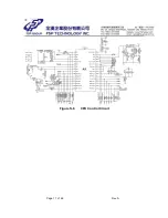
Page 18: ...Page 17 of 26 Rev A Figure S 6 CPU Control Circuit ...
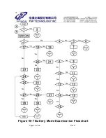
Page 26: ...Page 25 of 26 Rev A Figure W 7 Battery Mode Examination Flowchart ...
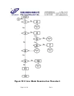
Page 27: ...Page 26 of 26 Rev A Figure W 8 Line Mode Examination Flowchart ...


