Page 11 of 26
Rev. A
5 Line and Zero- Crossing Detection
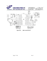
Please refer Figure S-4
5.1 Line Detection
The input voltage is fully rectified and generates a signal. The signal will be sent to
pin 11 of CPU through a voltage divider at R45, R45A and R40/ / R47. By monitoring
this rectified sinusoidal voltage, the CPU can identify if the utility is normal or
abnormal. There are two methods to evaluate if line voltage is abnormal.
5.1.1 Waveform detection:
I f
breakout occurs,
the CPU is able to immediately detect it and transfers
to battery mode. The waveform detection has a short response time.
5.1.2 RMS value detection:
CPU calculates input RMS value every cycle. I f RMS value is not in acceptable
range for 3 cycles, UPS will transfer to battery mode. Compared to waveform
detection, although it will take longer response time, the RMS value can be
accurately detected.
5.2 Zero Crossing Detection
Zero Crossing Detection is used to minimize the phase difference between
the I nverter voltage and the input line voltage while UPS is switched from battery
mode to line mode. I f the phase difference is too large, it will generate excess
energy which may damage the internal passive components such as relays.
The Zero Crossing signal is generated by the following conditions:
5.2.1 The signal of Line-I / P is full-bridge rectified waveform from line input.
The voltage of Pin 7 of I C324 drive Q14 (2222ASM) on or off.
5.2.2 The Zero Crossing signal comes from the collector of Q14 and goes
through MCU pin 27.
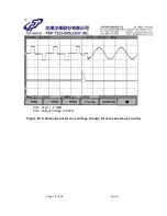
5.2.3 Refer to Figure W-2. The waveform of ZERO-CRO from Q14 collector and
Line-I / P.
Summary of Contents for EP450 series
Page 2: ...Page 1 of 26 Rev A UNINTERRUPTIBLE POWER SYSTEM SPECIFICATION EP450 650 850 Series ...
Page 9: ...Page 8 of 26 Rev A Figure S 2 Control Power Circuit CH1 C15 å GND Figure W 1 Cold Start ...
Page 11: ...Page 10 of 26 Rev A Figure S 3 B Charger Control Circuit ...
Page 18: ...Page 17 of 26 Rev A Figure S 6 CPU Control Circuit ...
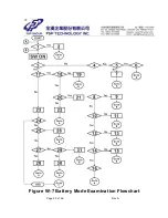
Page 26: ...Page 25 of 26 Rev A Figure W 7 Battery Mode Examination Flowchart ...
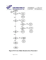
Page 27: ...Page 26 of 26 Rev A Figure W 8 Line Mode Examination Flowchart ...


