background image

19

10/2021 

21

2))

'9,,1

021,72

&9%6

,1387

*6',

,1387

*6',

/223287

9$&

+]

0(18

(17(5

3$7,(17

32:(5

):'

6723

3/$<3$86(

0(18

(17(5

3$7,(17

32:(5

):'

6723

3/$<3$86(

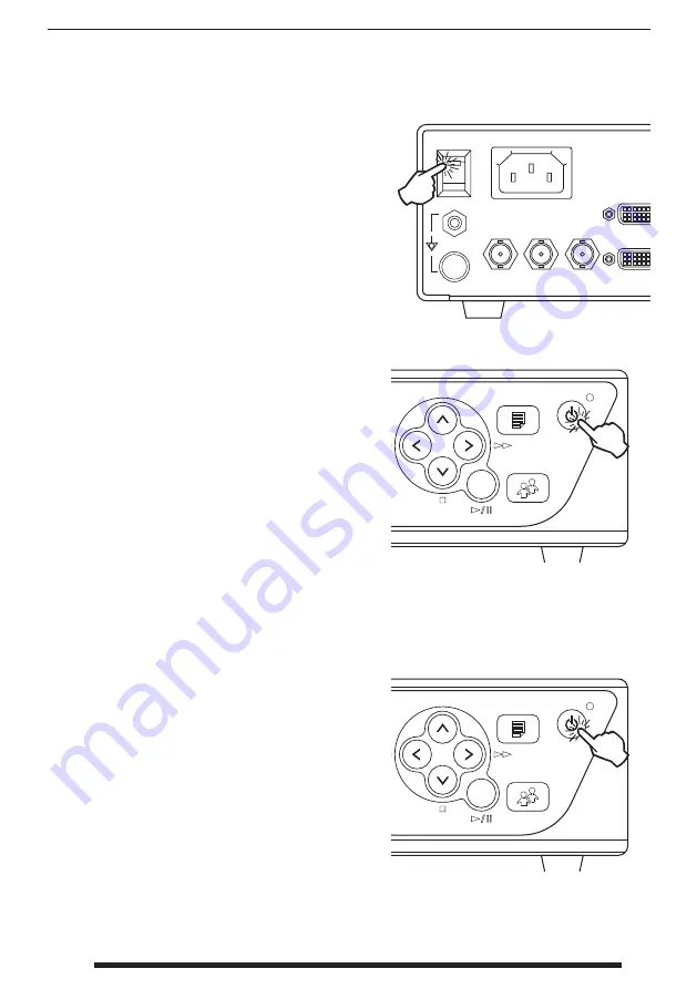
Turn Power On  IPS710A

Turn Power Off   IPS710A

Move the AC On/Off   switch on the back of 
IPS710 to the ON position. This will automatically 
start the initialization process.

If the back AC On/Off   switch is already in the ON 
position, and there is no image on the front LCD 
screen, and the upper right power status light is 
constant green, then press the power button on 
the unit’s front to start the initialization process.

Press the power button on the unit’s front and 
follow the directions on the front user interface.

Powering off  with this method will shut down 
the unit, however the back AC On/Off   switch will 
remain in the ON position.

Summary of Contents for IPS710A

Page 1: ...86 Before connecting operating or adjusting this product please read this instruction booklet carefully and completely English Image Processing System Instructions for Use IPS710A Video Recorder for Medical Use IPS740DS IPS740DG Video Recorder for Medical Use ...

Page 2: ...Us online at fsnmed com support eifu Table of Contents Product Description Intended Use 3 Symbol Definitions 4 Warnings Precautions 5 6 Safety Instructions 7 9 Electromagnetic Compatibility 10 14 Cleaning Instructions 47 IPS710A Accessories 15 Installation 16 18 Power On and Off 19 User Interface 20 25 General Specification 26 28 Dimensions 29 IPS740DS IPS740DG Accessories 30 Installation 31 33 Po...

Page 3: ...medical professional in a healthcare facility set ting where contact with a patient is unlikely no applied part This device is designed to meet the medical safety requirements for a patient vicinity device Warning This device may not be used in connection with life support equipment Indications for Use This device is to be used by a trained medical professional This device records and stores video...

Page 4: ...ctronic Temperature limitation Atmospheric pressure limitation Importer Entity UK Conformity Assessed Indicates proof of conformity to EU 2017 745 Medical Devices Regulation and applicable standards Medical Equipment is in accordance with ANSI AAMI ES60601 1 2005 AMD 1 2012 and CAN CSA C22 2 No 60601 1 2014 in regards to electric shock fire hazards and mechanical hazard Tested to comply with FCC C...

Page 5: ...o not expose this unit to rain or moisture Do not use this unit s polarized plug with an extension cord receptacle or other outlets unless the prongs can be fully inserted Underwriters Laboratories UL Classification UL safety Compliance This device is U L Classified WITH RESPECT TO ELECTRIC SHOCK FIRE AND MECHANICAL HAZ ARDS ONLY IN ACCORDANCE WITH UL 60601 1 CAN CSA C22 2 NO 601 1 EU Conformity a...

Page 6: ...fied or provided by the manufacturer of this equipment could result in increased electromagnetic emissions or decreased electromagnetic immunity of this equipment and result in improper operation Warning Portable RF communications equipment including peripherals such as antenna cables and external antennas should be used no closer than 30 cm 12 inches to any part of this device including cables sp...

Page 7: ...er if the set should be installed in an inaccessible area Warning Do not touch input or output connectors and the patient simultaneously Warning This device is intended for connection to input output signals and other connectors that comply with relevant IEC standard e g IEC60950 for IT equipment and IEC60601 series for medical electrical equipment In addition all such combination system shall com...

Page 8: ...se problems Max operating temperature is 40 C Don t use your device in direct sunlight and keep it away from heaters stoves fireplaces and sources of heat 5 Always use only the original cables and accessories with the device Repair Do not attempt to service the device yourself as opening or removing covers may expose you to dangerous voltages or other hazards and will void the warranty Refer all s...

Page 9: ...lass I including AC DC adapter This medical equipment is in accordance with ANSI AAMI ES60601 1 2005 AMD 1 2012 and CAN CSA C22 2 No 60601 1 2014 in regards to electric shock fire hazards and mechanical hazard Applied Parts No Applied Parts Degree of safety in the presence of flammable anesthetics mixture with air or with oxygen or with nitrous oxide Not suitable for use in the presence of a flamm...

Page 10: ...the receiving antenna 2 Increase the distance between the device and the subject of interference 3 Plug the device into an outlet on a different electrical circuit than that to which the subject of interference is connected 4 Consult the dealer or an experienced radio TV technician for help NOTICES TO USER This device complies with part 15 of the FCC Rules Operation is subject to the following two...

Page 11: ... that it is used in such an environment Interference immunity test IEC 60601 1 2 2014 con formity level Electromagnetic environment guidance Electrostatic discharge ESD acc to IEC 61000 4 2 Complies 2 kV 4 kV 6 kV 8 kV contact discharge 2 kV 4 kV 8 kV 15 kV air discharge Floors should be made of wood concrete or ceramic tile If floors are covered with synthetic material the relative humidity must ...

Page 12: ...0 to 470 GMRS 460 FRS 460 FM 5 kHz stroke 1 kHz sine wave 2 1 0 28 710 704 to 787 Band 13 17 Pulse modulation 217 Hz 0 2 1 0 9 745 780 810 800 to 960 GSM 800 900 TETRA 800 iDEN 820 CDMA 850 LTE Band 5 Pulse modulation 18 Hz 2 1 0 28 870 930 1720 1700 to 1990 GSM 1800 CDMA 1900 GSM 1900 DECT LTE Band 1 3 4 25 UMTS Pulse modulation 217 Hz 2 1 0 28 1845 1970 2450 2400 to 2570 Bluetooth WLAN 802 11 b ...

Page 13: ...tance in meters m The field strength of stationary transmitters at all frequencies on site a should be according to a study less than the conformity level b d 1 2 P 80 MHz to 800 MHz d 2 3 P 800 MHz to 2 5 GHz Interference may occur in the vicinity of equipment marked with the following symbol Note These guidelines may not apply in all situations The propagation of electromagnetic quantities is af...

Page 14: ... of the output power of the communication device as shown below Nominal power of transmitter W Separation distanced m according to frequency of transmitter 150kHz to 80 MHz d 1 2 P 80 MHz to 800 MHz d 1 2 P 800 MHz to 2 5 GHz d 2 3 P 0 01 0 12 0 12 0 23 0 1 0 38 0 38 0 73 1 1 2 1 2 2 3 10 3 8 3 8 7 3 100 12 12 23 For transmitters rated at a maximum output power not listed above the recommended sep...

Page 15: ...15 10 2021 3 2 1 4 5 6 Accessories IPS710A Item Description Pack Qty 1 Shipping box 1 2 Packaging cushion 1 3 User s guide 1 4 AC power Cord 6ft Medical Grade 1 5 DVI D cable 6ft 1 6 IPS710A unit 1 ...

Page 16: ...ind button 20 DVI input DVI D up to WUXGA 6 Up button 21 MIC in 3 5ø phone 7 Down Stop button 22 Line audio in 3 5ø phone 8 Right Forward button 23 Speaker function alarm playback sound 9 Enter Play Pause button 24 Line audio out 3 5ø phone 10 Menu button 25 Pedal input capture 3 5ø phone 11 Patient button 26 Pedal input recording 3 5ø phone 12 Power button 27 Network port RJ45 13 AC On Off switch...

Page 17: ...als as DVI D SDI and CVBS Specific applications will determine the type of input signal sources that will be connected to IPS710A Never use this system with damaged cables Keep all cables away from areas where they may cause tripping The Monitor Out connection on IPS710A is used to display the external monitor user interface including controls for live video recorded images patient information ses...

Page 18: ...cal Switch IPS710A Only use the specified plug and voltage Power requirements are AC 100 240V 50 60Hz 2A max Use the supplied 6 ft hospital grade AC power cord Improper power may cause electric shock or equipment damage To avoid the risk of electric shock this equipment must only be connected to a power supply with protective grounding Use the Audio In jack to connect an input sound device such as...

Page 19: ...ization process If the back AC On Off switch is already in the ON position and there is no image on the front LCD screen and the upper right power status light is constant green then press the power button on the unit s front to start the initialization process Press the power button on the unit s front and follow the directions on the front user interface Powering off with this method will shut d...

Page 20: ...e LCD can also be used as a secondary method to adjust some user interface op tions for File List Audio Video Information and Setup To navigate the front user interface select ENTER to move to the next screen confirm a value or play a file Select MENU to go back to the previous screen or back to live preview Use the left or right arrow buttons to scroll through the available menu screens Press the...

Page 21: ...r Interface IPS710A When an external monitor is connected to IPS710A a built in interface will show on the moni tor after IPS710A has initialized This interface can be controlled with a mouse and keyboard attached to IPS710A or by using a touchscreen external monitor External monitor is connected to the DVI out port USB mouse and keyboard if conventional monitor is used USB cable if touchscreen mo...

Page 22: ...elete task content Delete task AV settings Record settings FTP settings DICOM settings Network settings System settings Create new task Enter patient details Capture still images View four most recent captures Record video Access modality worklist Top Status Bar Each screen in the user interface shows a top bar with current information for available memory available recording time remaining and th...

Page 23: ...grate protocols such as FTP Samba DICOM network addresses etc Setup video signal type and resolution audio input type Setup recording quality clip size simultaneous copy to USB USB speed check still capture file format Setup FTP server and Samba client Setup worklist and MPPS Setup store server details source modality station title and character set Setup date and time or GMT Setup network DHCP IP...

Page 24: ...enerated The most recent still captures will be displayed on the dashboard Press and hold as a shortcut to several commands Press to capture a still image Press to begin video recording The record ing icon will turn red Press again to stop recording View active source Close task when all recordings are completed View most recent still capture full screen Double tap to return to dashboard When crea...

Page 25: ...ce for full screen view Click a full screen view once to return to the task list Full screen video file ready for playback All other button functions are performed according to the button label and Setup dashboard options Still image files Press the Task List button to open the dashboard where all tasks and file thumbnails can be viewed All tasks stored on the internal hard disk drive are listed h...

Page 26: ... in Line in Note Only single input DVI SDI or Composite can be recorded Outputs Monitor output DVI D Loop out 3G SDI Audio 3 5mm Stereo x 1ea Line out Data I O USB2 0 Front 1 Rear 3 RS 232C DB9 female connector x 1ea Ethernet RJ45 x 2ea 10 100 1000M Keyboard Mouse USB type Foot pedal 3 5mm stereo jack x 2ea Record Capture Recording Capture Recording resolution 480P60 720P60 1080P60 Video format AV...

Page 27: ...ertifications UL 60601 1 EN 60601 CE MDD 93 42 EEC ISO 9001 ISO 13485 Class 1 Medical Device RoHS Item Signal Name Type Supported Resolution Application Signal Input DVI in DVI24 Up to 1920x1200 60 Endoscopic camera PC SDI in BNC Up to 1080p Endoscopic camera CVBS in BNC NTSC PAL Endoscopic camera Signal Output SDI loop out BNC Up to 1080p Surgical Monitor Network Network RJ45 FTP CIFS Network PC ...

Page 28: ...00 1280 X 1024 75Hz 80 00 75 00 135 00 1360 X 768 60Hz 47 72 60 00 84 75 480p 31 50 60 00 27 03 720p 45 00 60 00 74 25 1080i 33 75 60 00 74 25 1080p 67 50 60 00 148 50 1920 x 1200 60Hz 74 12 60 00 154 25 DVI input CVBS input SDI input output Signal in Description Video NTSC PAL Signal in out Description SMPTE 424M 1080p SMPTE 292M 720p 1080i SMPTE 259M 480i 576i Power Consumption IPS710A Mode Cons...

Page 29: ...29 10 2021 5 25 0 18 17 5 3785 3 7 17 32 5 5 6723 3 3 86 PP LQ PP LQ PP LQ Dimensions IPS710A ...

Page 30: ...wer cord 6ft 1 8 m medical grade User s guide HDMI cable 2 m DisplayPort cable 6ft 1 8 m IPS740DS IPS740DG 1 SDI cable 4 SDI cables 6ft 1 8 m 6ft 1 8 m Packaging cushion Shipping box IPS740DS or IPS740DG unit Accessories IPS740 series ...

Page 31: ... be initiated by using an attached monitor touchscreen or mouse or with VACS software POWER on off button With the back panel power switch in the ON position press to start the initialization process LED indicator when the back panel power switch in the ON position Green standby Off Unit is working normally SETUP icon opens settings for input sources file types DICOM server net work local time foo...

Page 32: ...et 15 HDMI Output 1920x1080p 60 3840x2160p 60 4 DC Inlet For use as an auxiliary power supply to prevent file errors during recording when a power failure occurs 16 PEDAL Input Capture 3 5mm 5 3G SDI4 Input BNC 75Ω 17 PEDAL Input Record 3 5mm 6 3G SDI4 loop throughout BNC 75Ω 18 LINE AUDIO Output 3 5mm 7 3G SDI3 Input BNC 75Ω 19 MIC Input 3 5ø phone 8 3G SDI3 loop throughout BNC 75Ω 20 LINE AUDIO ...

Page 33: ...o back of recorder Connect to back of recorder Video source Active signal is previewed on the front panel LCD Tap the LCD to show icons for Home File Worklist Setup Monitor if connected Task create new or close active Active signal and icons are previewed on the connected external monitor Use the front panel LCD as a touchpad to move the cursor and select items on the external monitor ...

Page 34: ...ve the AC On Off switch on the back panel to the ON position Press the power button on the front panel to start the initialization process Press the power button on the front panel and follow the directions on the user interface Powering off with this method will shut down the unit however the back AC On Off switch will remain in the ON position ...

Page 35: ...3 06 GB H 3 39 TB 2019 10 23 08 58 Date Time Data Storage Capacity IPS740 series Front Panel LCD External Monitor Current date and time Internal hard disk drive remaining capacity USB memory stick remaining capacity ...

Page 36: ...s automatically given by the system to each new task The Create Task dialog asks for the following information Patient ID Patient Name Patient Sex Patient Birth Date Task Description This information can be entered manually using the interface keyboard or an attached USB keyboard The information can also be imported from a facility s worklist as described later in this guide Create New Task Close ...

Page 37: ...Monitor External Monitor Select to close a task Note the sign in the icon means that a task is currently active Select to close a task Select the FILE icon to manage tasks including search modify copy delete DICOM store and print After a task has been closed additional content can no longer be added to the task ...

Page 38: ...he camera icon to capture an image A beep sound signals that the capture was performed A preview of the capture is displayed for 1 5 seconds If a foot pedal is connected to the pedal capture input on the back of the recorder pressing the pedal will capture a still image Captured still images are stored within the task for future use Select the video recorder icon to record video A beep sound and r...

Page 39: ...gnifying glass icon to search tasks for specific content Front Panel LCD External Monitor Task Actions Copy to USB Copies the selected task to a USB memory stick All USB memory sticks plugged in the system will be shown as options Delete Deletes the selected task DICOM Store Sends the selected task to the PACS server Print Prints the selected task The printing layout 1x1 Landscape for example is s...

Page 40: ...lecting files to be manipulated Copy to USB Copies the selected files to a USB memory stick All USB memory sticks plugged in the system will be shown as options Delete Deletes the selected files DICOM Store Sends the selected files to the PACS server Print Prints the selected files The printing layout 1x1 Landscape for example is shown on the title bar of the dialog window Modify Allows changes to...

Page 41: ...o files are marked with a film symbol and are opened with the play icon Click play to start as the video is played back the progress bar increases Front Panel LCD Front Panel LCD External Monitor External Monitor Captured still images are viewed full screen Recorded videos are viewed full screen with controls at the bottom Click play to start as the video is played back the progress bar increases ...

Page 42: ...mation that is stored on the worklist server will be presented in the left window Click a worklist item and detailed information associated with the item is presented in the right window Front Panel LCD External Monitor Left Column Patients on the worklist Right Column After a selection patient information details Create Task Click to convert a worklist item into a recorder task Start MPPS Modalit...

Page 43: ...lip Size USB Auto Copy Capture Format USB Auto Copy DICOM Common Resolution Aspect Ratio Worklist Server AE Title Server IP Server Port Client AE Title Echo Store Server AE Title Server IP Server Port MPPS Server AE Title Server IP Client AE Title Echo Common Modality Hospital Institution Scheduled Station AE Title Character Set CIFS Samba ID Password Network DHCP IP Netmask Gateway DNS Time Time ...

Page 44: ...l 3 5mm stereo jack x 2ea Record Capture Recording Capture Recording resolution 1920x1080p60 3840x2160p60 Encoding formats H 264 H 265 Recording file format MP4 Capture image format BMP JPEG DICOM Audio encoding format AAC 3D video formats 4K line alternative SBSH conversion 4K side by side half Storage Internal hard drive 4TB External USB storage USB flash drive USB HDD USB file system FAT32 NTFS...

Page 45: ...096 x 2160p 135 00 60 00 594 00 HDMI output Resolution Horizontal Frequency KHz Vertical Frequency Hz Clock Frequency MHz 1920 X 1080 60Hz 67 5 60 0 148 5 3840 X 2160 60Hz 135 0 60 0 594 0 DisplayPort input Resolution Horizontal Frequency KHz Vertical Frequency Hz Clock Frequency MHz 1080p 67 50 60 00 148 50 3840 x 2160p 135 00 60 00 594 00 4096 x 2160p 135 00 60 00 594 00 SDI input Signal input D...

Page 46: ...46 10 2021 21 2 6 1387 9 1 9 287387 3 1387 0 1387 02 2 21 2 6 1387 9 1 9 287387 1 3 1387 0 1387 02 2 32 5 5 25 3785 32 5 5 25 3785 PP LQ PP LQ PP LQ Dimensions IPS740 series ...

Page 47: ... with a recognized cleaning product for medical equipment 2 Repeat with water only 3 Wipe dry with a dry cloth The cabinet has been tested for resistance to the following products Virex Ready to use Disinfectant Cleaner Misty Clear Lemon 10 Disinfectant Misty Multi Purpose Disinfectant Cleaner Misty Multi Purpose Disinfectant Cleaner II Zep Heavy duty glass all surface cleaner Klear Screen Screen ...

Page 48: ...UK Ltd 1 Wolsey Road East Molesey Surrey KT8 9EL United Kingdom Tel 44 0 208 546 1047 FORESEESON KOREA 404B Pangyoinnovalley B 253 Pangyo ro Bundang gu Seongnam si Gyeonggi do Korea 463 400 Tel 82 31 8018 0780 Fax 82 31 8018 0786 FORESEESON Shanghai Medical Equipment Co Ltd Room 307 3F No 56 461 Hongcao Road Caohejing Development District Xuhui Shanghai 200233 Tel 86 21 6113 4188 FORESEESON CUSTOM...

Reviews: