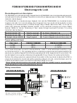
FEM3500/FEM3500D/FEM3500M/FEM3500DM
Electromagnetic Lock
Electro-Magnetic Lock Description:
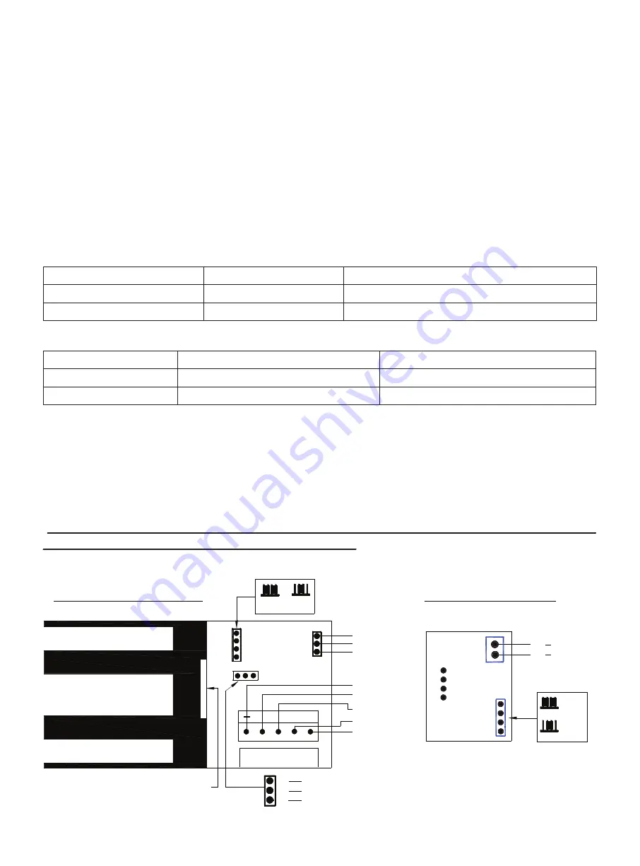
Power setting and Input
Wiring connections:
The FEM3500 is an unmonitored single magnetic lock and FEM3500D is an unmonitored double magnetic
lock with dual 12 or 24 volt settings. There are no Lock or Door status sensors on these units. For wiring
instruction refer to figure 2.
The FEM3500M is a monitored single magnetic lock and the FEM3500DM is a monitored double
magnetic lock with 12 or 24 volt settings. Each magnetic lock has a built-in Hall crystal for remote
monitoring of Lock status (open or closed) through relay contacts rated at 24 VDC, 1.0 A max on
visible high luminosity backlight indicator position on the aluminum housing and a Door Status
Sensors (DSS) for remote monitoring of Door status through reed switch contact. For wiring
instruction refer to Figure 1.
The (+) lead of the power source is connected to Pins 1 (VDC +) of the terminal block and the (-) lead
is connected to Pin 2 (-). The operating switch or controlling contacts must be installed between the
power source and the magnetic lock to reduce operating time of the magnetic lock to a minimum. The
electromagnetic lock requires a filtered and regulated DC Power Source for optimal performance.
Remove the wiring cavity cover plate and check the position of the two shunts located on the PCB. A
single shunt across pins 2 and 3 will set the operating voltage to 24 volts. A shunt between pins 1 to
2 and a shunt between pins 3 to 4 sets the operating voltage to 12 volts.
These voltage shunts must be set correctly before 12 VDC or 24 VDC power is supplied to the
Electromagnetic Lock to prevent damage to the unit.
1 2 3 4
1 2 3 4
-
_
LED LIGHT PANEL
R
B
G
R B G
HIC
VDC
C
NC
NO
C
NC
NO
+ 12/ 24 VDC
12/ 24 VDC
LED
GREEN
BLACK
RED
R
B
G
GREEN
BLACK
RED
DSS WIRING: BLUE, BLUE
(
NORMALLY OPEN
)
DSS contact rating: 30 VDC
,
0.2 Amp max.
12 VDC
24 VDC
FEM3500/ FEM3500D PCB
1
2
3
4
GROUND
VOLTAGE
+
-
R
G
B
W
Figure 2
12 VDC
24 VDC
1 2 3 4
1 2 3 4
FEM3500M/ FEM3500DM PCB
Figure 1
Power Input
FEM3500/ FEM3500M
FEM3500D/ FEM3500DM
0.50 A
0.25 A
2 x 0.50 A
2 × 0.25 A
12 VDC
24 VDC
Backlight Indicator OFF
Relay De-energized,
No Power on Magnetic Lock
Relay De-energized,
Relay Energized,
Power on Magnetic Lock and Door is Open.
Power on Magnetic Lock and Door Locked.
Backlight Indicator RED
Backlight Indicator GREEN
Summary of Contents for FEM3500
Page 3: ......


