Frymaster 8196203 Installation, Operation, Service, And Parts Manual Download Page 29

6-4 


6.2.2  Error Messages and Display Problems 
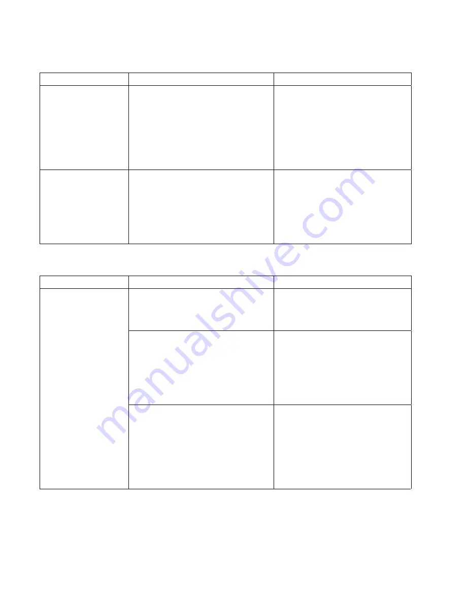
 

Problem 

Probable Causes 

Corrective Action 

Controller trouble 

light ON.


Oil temperature above acceptable 
range or a problem with the 
temperature measuring circuitry. 

This in an indication of a 
malfunction in the temperature 
measuring or control circuitry, 
including a failure of the high limit 
thermostat.  Determining the 
specific problem is beyond the 
scope of operator troubleshooting.  
Shut the fryer down immediately. 

Controller trouble 

light ON and heating 

mode light ON.


Open drain valve or problem with 
latching circuits 

Verify that the drain valve is fully 
closed.  The fryer will not function 
if the drain valve is not fully 
closed.  If the drain valve is fully 
closed, the problem is within the 
latching circuitry and is beyond the 
scope of operator troubleshooting. 

 
6.2.3 Filtration 

Problems 


Problem 

Probable Causes 

Corrective Action 

A.


Power cord is not plugged in or 
circuit breaker is tripped. 

A.


Verify that the power cord is 
fully plugged in.  If so, verify 
that circuit breaker is not 
tripped. 

B.


Pump motor has overheated 
causing the thermal overload 
switch to trip. 

B.


If the motor is too hot to touch 
for more than a few seconds, the 
thermal overload switch has 
probably tripped.  Allow the 
motor to cool at least 20 
minutes then press the Pump 
Reset Switch. 

Filter pump won't 

start. 


C.


Blockage in filter pump. 


Test:  

Close the drain valve and 

pull the filter pan out from the 
fryer.  Activate the pump.  If the 
pump motor hums for a short time 
then stops, the probable cause is 
blockage of the pump itself.


C.


Pump blockages are usually 
caused by sediment buildup in 
the pump due to improperly 
sized or installed filter paper 
and failure to use the crumb 
screen. 


(continued on following page) 

Summary of Contents for 8196203

Page 1: ...ster com 8196203 This manual is applicable to fryers manufactured beginning May 2006 with serial numbers beginning with 0604 For serial numbers between 0308 to 0604 refer to manual 819 6004 For serial...

Page 2: ...g diagrams furnished with the equipment Wiring diagrams are located on the inside of the fryer door DANGER Do not store or use gasoline or other flammable vapors and liquids in the vicinity of this or...

Page 3: ...eived including interference that may cause undesired operation While this device is a verified Class A device it has been shown to meet the Class B limits CANADA This digital apparatus does not excee...

Page 4: ...F CONTENTS Page Chapter 1 Introduction 1 1 Chapter 2 Installation Instructions 2 1 Chapter 3 Operating Instructions 3 1 Chapter 4 Filtration Instructions 4 1 Chapter 5 Preventive Maintenance 5 1 Chapt...

Page 5: ...e fryers 1 2 Safety Information Before attempting to operate your unit read the instructions in this manual thoroughly Throughout this manual you will find notations enclosed in double bordered boxes...

Page 6: ...uipment was carefully inspected and packed by skilled personnel before leaving the factory The freight company assumes full responsibility for safe delivery upon acceptance of the equipment 1 File Cla...

Page 7: ...aint devices DANGER Adequate means must be provided to limit the movement of this appliance without depending on or transmitting stress to the electrical conduit NOTICE If this equipment is wired dire...

Page 8: ...til power is restored A clearance of 6 inches 15cm must be provided at both sides and back adjacent to combustible construction A minimum of 24 inches 61cm should be provided at the front of the equip...

Page 9: ...nce must be connected to a power supply having the same voltage and phase as specified on the rating plate located on the inside of the appliance door DANGER All wiring connections for this appliance...

Page 10: ...h the instructions in Section 5 1 3 of this manual 3 Drain clean and fill frypot s with cooking oil See Equipment Setup and Shutdown Procedures in Chapter 3 2 5 Dimensions and Weights Single Fryer wit...

Page 11: ...7 534 20 48 10 580 2 465 15 67 20 48 Front Handle Mounting Holes 625 4 Places Single Fryer non filter 31 62 7 098 Typical 2 470 26 316 17 515 33 39 31 45 31 62 Back of Fryer Unit Front Handle Mounting...

Page 12: ...66 47 1 22 66 22 66 Front Handle Back of Fryer Unit Mounting Holes 625 4 Places 3 Fryer Battery 2 470 7 119 17 490 62 55 31 180 7 119 33 45 31 61 31 61 Front Handle 26 320 35 76 35 76 Back of Fryer Un...

Page 13: ...ck the shortening around and over the elements It may be necessary to add shortening to bring the level up to the proper mark after the packed shortening has melted DANGER Never set a complete block o...

Page 14: ...s over high limit or problem in heat control circuitry 5 Thermostat Control Knob Sets desired frying temperature 6 Hi Limit Test Switch Tests high limit thermostat 7 Second Hi Limit Test Light Indicat...

Page 15: ...OCEDURE Tools Required One 0 600 F pyrometer with sensing probe or an equivalent high temperature thermometer NOTE Conduct this test when the fryer will not be needed for about one hour and when the c...

Page 16: ...and all control panel lights should have been extinguished For fryers not connected to an external shunt power supply only the fryer being tested should have been shut off 5 Place the controller power...

Page 17: ...rs the filter pan then pull the pan out from the cabinet Remove the crumb tray hold down ring and filter screen Clean all components with a solution of detergent and hot water then dry thoroughly The...

Page 18: ...e accomplished with care to avoid the possibility of a serious burn caused by careless handling The oil to be filtered is at or near 350 F Ensure drain handles are in their proper position before oper...

Page 19: ...to and through the frypot during a 5 minute process called polishing Polishing cleans the oil by trapping solid particles in the filter medium 6 After the oil is filtered about 5 minutes close the dra...

Page 20: ...AL container for transport to the disposal container Frymaster recommends the use of the Frymaster Shortening Disposal Unit SDU NOTE If using an SDU built before January 2004 the filter pan cover must...

Page 21: ...faces Read the directions for use and precautionary statements before use Particular attention must be paid to the concentration of cleaner and the length of time the cleaner remains on the food conta...

Page 22: ...ture control knob to the lowest setting 4 Simmer the solution for 45 minutes to one hour Do not allow the water level to drop below the bottom oil level line in the frypot during the boil out operatio...

Page 23: ...r the temperature sensing probe approximately five inches deep into the cooking oil When the heating elements cycle on for the fourth time the thermometer should read within 5 F of the temperature con...

Page 24: ...rature and high limit probes are properly connected tightened and functioning properly and that mounting hardware and probe guards are present and properly installed Verify that component box and cont...

Page 25: ...il return valves i e place all oil return handles in the OFF position Verify proper functioning of each oil return valve by activating the filter pump using the lever on one of the oil return handle m...

Page 26: ...to ensure that it doesn t happen again If a controller malfunctions because of a poor connection check all other connections too If a fuse continues to blow find out why Always keep in mind that failu...

Page 27: ...s beyond the scope of operator troubleshooting Call FASC A Drain valve is open A This fryer is equipped with a drain safety switch that prevents the heating element from being energized if the drain v...

Page 28: ...ute controller functions correctly order a new controller If substitution of the controller does not resolve the problem the most likely cause is a failed temperature probe Fryer heats until high limi...

Page 29: ...d is beyond the scope of operator troubleshooting 6 2 3 Filtration Problems Problem Probable Causes Corrective Action A Power cord is not plugged in or circuit breaker is tripped A Verify that the pow...

Page 30: ...moved call FASC A Improperly installed filter pan components A Verify that filter screen is in bottom of pan with paper top of screen Verify that O rings are present and in good condition on filter pa...

Page 31: ...harness from the connector on the back of the controller and disconnect the grounding wire from terminal adjacent to the connector Remove the control panel assembly by lifting it from the hinged slot...

Page 32: ...in the component box Remove these three screws at each end Remove these two screws from the center supports Removing the Control Panel Frame and Top Cap Assembly 5 Reconnect the wiring disconnected i...

Page 33: ...ties to secure any loose wires 9 Reinstall the back panels reposition the fryer under the exhaust hood and reconnect it to the electrical power supply to return the fryer to service 7 5 Replacing a Te...

Page 34: ...low For full vat units or the right half of a dual vat unit as viewed from the rear of the fryer the red lead goes into position 3 and the white lead into position 4 of the connector For the left half...

Page 35: ...For full vat units remove the element clamps before removing the nuts and screws that secure the element to the tube assembly 6 If applicable recover the probe bracket and probe from the element being...

Page 36: ...s 1 If replacing a contactor box component above the built in filter system remove the filter pan and lid from the unit Drain the frypots into a Shortening Disposal Unit SDU or other appropriate metal...

Page 37: ...ttom tabs then slide the bezel down to disengage the upper tabs 4 Remove the two screws from the upper corners of the control panels and allow them to swing down see illustration and photo on page 7 1...

Page 38: ...es or tape 19 Carefully lift the frypot from the fryer and place it upside down on a stable work surface 20 Recover the drain valve s oil return flexline connection fitting s and high limit thermostat...

Page 39: ...e bottom of the filter pan is present and in good condition A missing or worn O ring allows the pump to take in air and decreases its efficiency Also oil leaks on the floor each time a vat is drained...

Page 40: ...suction tube on the bottom of the filter pan Particles large enough to block the suction tube may indicate that the crumb tray is not being used Pan blockage can also occur if shortening is left in th...

Page 41: ...loor Once on the floor pull the assembly out the front of the fryer 9 When required service has been completed reverse steps 6 12 to reinstall the bridge NOTE The black motor wires go on the top termi...

Page 42: ...om the fryer to expose the interior of the left component box The filter transformer and relay are located as shown in the illustration below NOTE The right component box is identical to the left exce...

Page 43: ...controller before testing the probe circuit Diagnostic LED Legend CMP indicates power from 12V transformer 24 indicates power from 24V transformer HI RH indicates output closed from right latch relay...

Page 44: ...1 27 150 1247 66 220 1391 104 290 1534 143 360 1674 182 85 1112 29 155 1258 68 225 1402 107 295 1544 146 365 1684 185 90 1122 32 160 1268 71 230 1412 110 300 1554 149 370 1694 188 95 1133 35 165 1278...

Page 45: ...7 15 7 12 Wiring Diagram System H14SC H17SC H22SC kW Single Fryers and FPH17SC kW Filter System Fryers 440 480V 60 Hz 3 3 Wire Configurations Refer to page 2 2 for power requirements...

Page 46: ...7 16 7 13 Wiring Diagram Contactor Box H14SC H17SC H22SC kW Single Fryers and FPH17SC kW Filter System Fryers 440 480V 60 Hz 3 3 Wire Configurations Refer to page 2 2 for power requirements...

Page 47: ...7 17 7 13 Wiring Diagram Contactor Box cont H14SC H17SC H22SC kW Single Fryers and FPH17SC kW Filter System Fryers 440 480V 60 Hz 3 3 Wire Configurations Refer to page 2 2 for power requirements...

Page 48: ...7 18 7 14 Wiring Diagram Wiring Harness...

Page 49: ...Dual vat oil return switch When the return valve is open the 24V circuit is closed and it activates the pump relay and drain solenoid E Optional waste oil pump switch The drain valves and oil return...

Page 50: ...3 809 0921 Spacer Basket Hanger 4 803 0197 Cleanout Rod 27 inch 5 803 0209 Brush Frypot 6 823 6009 Connecting Strip Frypot 7 806 4041 Cover Full Vat Frypot 8 803 0132 Rack Full Vat Basket Support 9 8...

Page 51: ...8 2 8 2 Cabinetry 8 2 1 Backs Control Panels Doors Handles Sides Tilt Housings Top Caps 4 6 1 2 3 5 9 10 11 8 7 12 14 13...

Page 52: ...low plus 210 9214 824 1516 Door Universal Single 210 9215 Liner Door Universal Single 809 0500 Screw 10 Hex TR HD SS 826 1343 Spring Door Pin Hinge Pkg of 10 210 9188 Hinge Door Single 106 4769 Door L...

Page 53: ...8 4 8 2 2 Cabinets Bases Braces and Associated Parts See Page 8 22 through 8 24 for filter rails and associated hardware See Page 8 26 for rear bridge support oil return manifold...

Page 54: ...actor box 16 826 1376 Nut 10 32 Keps Hex Pkg of 10 17 826 1374 Screw 10 X inch Hex Washer Head Primary cabinet screw Qty 25 18 809 0417 Nut 20 Hex Flange used with item 22 19 809 0429 Bolt 20 X 2 inch...

Page 55: ...8 6 8 3 Drain System Components 8 3 1 Drain Tube Sections and Associated Parts 8 7 7 6 6 1 3 3 4 4 5 2 2 1 See next section for Drain Valve Detail...

Page 56: ...t 3 3 Drain Tube Right End Long 823 4639 Full Vat 3 823 4638 Dual Vat 3 4 Drain Tube Left Right Open Long 823 4641 Full Vat 3 823 4640 Dual Vat 3 5 823 4892 Drain Outlet Center Dump 6 816 0625 Sleeve...

Page 57: ...d Handle 5 809 0237 Nut 4 40 Keps Hex 6 901 2348 Cover Dual Vat Drain Safety Switch 7 807 2103 Microswitch CE Straight Lever 8 816 0220 Insulation Drain Safety Switch 9 806 8137SP Bracket Assembly Ful...

Page 58: ...Vat Drain Valve 4 816 0639 Cap Red Handle 5 809 0237 Nut 4 40 Keps Hex 6 901 2348 Cover Dual Vat Drain Safety Switch 7 807 2103 Microswitch CE Straight Lever 8 816 0220 Insulation Drain Safety Switch...

Page 59: ...8 10 8 3 2 Drain Valve Assembly and Assoc Parts cont Units with Built In Filtration...

Page 60: ...r Teflon Drain Valve 10 809 0196 Washer inch Flat 11 106 2671 Bracket Assembly Dual Vat Drain Safety Switch 106 6304 Bracket Assembly Dual Vat Drain Safety Switch Single Footprint Only 12 810 1114 Val...

Page 61: ...440 480 12 24V Used in non filter fryers 12 809 0349 Spacer 4mm X 6mm Aluminum 13 106 6811 Interface Board on SMT boards the Relays are not replaceable 807 3932 Relay Heat Latch 12VDC SPDT 12 Amp Seal...

Page 62: ...3868 Strain Relief 21 807 0121 Bushing Heyco SB 625 500 22 816 0217 Paper Insulating Terminal Block CE 23 106 5750 Harness Full Vat Assembly 24 220 0083 Plate Strain Relief 25 807 4036 Switch 807 357...

Page 63: ...assemblies are mirror images of one another With the exception of the box itself all components of a left hand assembly are the same as those in the corresponding right hand assembly and vice versa N...

Page 64: ...02 Contactor 24V 40 Amp Mechanical 8 807 2283 Contactor 24V 63 Amp Mechanical used in 22kW units only 9 807 2434 Relay Shunt 24V Coil Amp 10 807 1683 Relay Power 12 VDC 11 807 0012 Relay Tilt 18 Amp H...

Page 65: ...NOTES The only difference between element assemblies for different voltage and kW ratings is the element itself Item 1 Items 28 29 and 30 are shown as associated parts They are not part of either ass...

Page 66: ...et Assembly LH Upper Spring 14 106 6570 Bracket Assembly RH Upper Spring 15 826 1330 Screw 10 32 X inch Slotted Truss Head SS Pkg of 25 16 809 0766 Nut 10 32 Hex HD SS 17 809 1000 Screw 10 32 x 1 inch...

Page 67: ...troller P N 806 3798 Knob P N 810 0387 Power Switch P N 807 0812 High Limit Switch P N 807 0811 8 4 5 Wiring 8 4 5 1 Contactor Box Wiring Assembly 12 Pin Full Vat C 1 8 4 5 2 Contactor Box Wiring Asse...

Page 68: ...8 4 5 4 Main Wiring Harness 8 4 5 5 Component Box and Filter Pump Wiring Harnesses ITEM PART COMPONENT 1 106 5750 Full Vat Control Harness J4 to J2 WIR0765 Navy Jumper Wire Kit is needed with this ha...

Page 69: ...8 20 8 4 5 6 Interface Board to Controller Wiring Harness 15 Pin PN 806 2071SP Standard Controller to Interface Board...

Page 70: ...8 21 8 5 Filtration System Components 8 5 1 FPH17 Filtration Components...

Page 71: ...r includes one left and one right 7 826 1392 O Ring Pkg of 5 used with Item 5 8 106 5981 Support Assy Left Filter Pan 9 106 5982 Support Assy Right Filter Pan 10 823 5591 Fitting Female Suction Tube 1...

Page 72: ...8 23 8 5 2 Multiple Battery Filtration System Components 5 6 13 14 15 7 12 11 9 12 11 10 16 30 29 25 27 26 24 23 18 24 18 35 19 33 17 20 22 25 34 28 8 32 31 1 2 3 4 8 21...

Page 73: ...r Pan Lid 11 809 0503 Screw 8 32 X inch Slotted Truss Head 12 809 0247 Nut 8 32 Hex Keps 13 823 3879 Suction Tube 14 200 4408 Rail Left Filter 15 200 4409 Rail Right Filter 16 826 1712 Kit Motor and G...

Page 74: ...8 25 8 6 Frypot Assembly and Thermostat Frypot P N 823 5359SP Thermostat P N 806 7543...

Page 75: ...8 26 8 7 Oil Return System Components...

Page 76: ...Valve Handle 10 809 0601 Clip Clevis 11 810 2532 Flexline 7 0 inch 12 810 1668 Adapter inch to inch NPT Male 13a 813 0165 Elbow inch X 90 Street 13b 813 0908 Adapter inch NPT M T 90 used only on side...

Page 77: ...er Connectors 1 807 1068 2 Pin Female 2 807 0158 6 Pin Female 3 807 0156 9 Pin Female 5 807 0159 12 Pin Female 5 807 0875 15 Pin Female 6 807 1067 2 Pin Male 7 807 0157 6 Pin Male 8 807 0155 9 Pin Mal...

Page 78: ...0 Screw 8 x inch Hex Washer Slot Head 826 1371 Screw 8 x inch Hex Head ZP Pkg of 25 809 0361 809 0364 Screw 8 x inch Hex Washer Head ZP 809 0518 Screw 8 32 x inch Hex Washer Slotted Head SS 809 0104 S...

Page 79: ...THIS PAGE INTENTIONALLY LEFT BLANK...

Page 80: ...aster L L C 8700 Line Avenue Shreveport LA 71106 TEL 1 318 865 1711 FAX Parts 1 318 688 2200 Tech Support 1 318 219 7135 819 6203 PRINTED IN THE UNITED STATES SERVICE HOTLINE 1 800 551 8633 NOVEMBER 2...

Reviews: