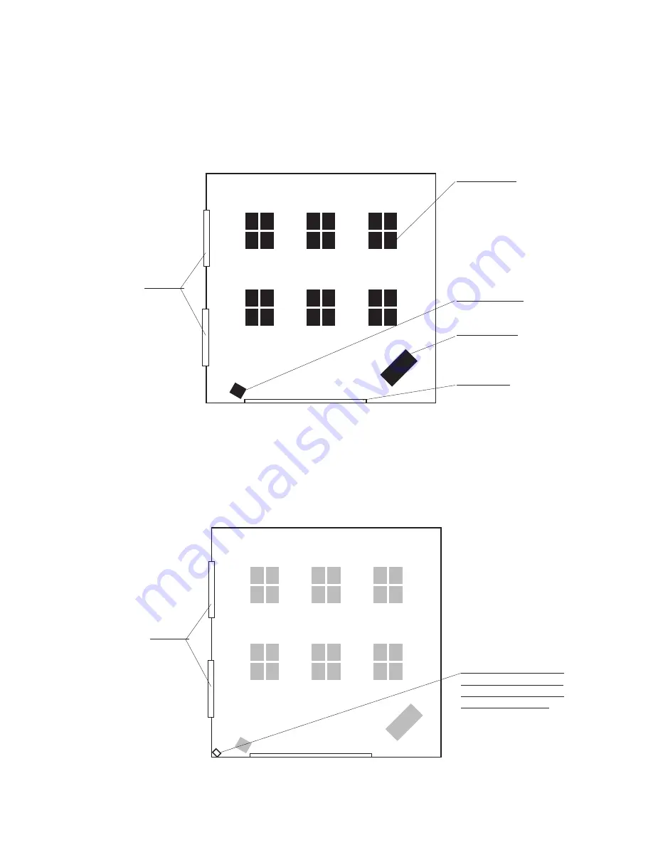
background image

Student desks

Teacher’s desk

TV / VCR / DVD

White board

Top view of an example classroom

Windows

A good place for the receiver

You’ll install the receiver 
at teacher eye-level in a 
corner from which it can 
‘see’ the whole room

Windows

7

Step 3:

  Plan your installation (Speakers)

Estimated time for this step: 5-10 minutes

Your classroom is ready and you’ve organized all the parts and tools you’ll need to set up your active learning 
system. Now it’s time to decide where you’ll place major components. To help you decide, we’ll use the  
following layout of a typical classroom as an example:

1.  Decide where to put the receiver

We recommend locating the receiver in a corner with good visibility of the classroom, at about the teacher’s eye-level.

If you’re going to be connecting other audio sources to your receiver (see Before You Begin), consider a location 
near the teacher’s computer or TV/VCR/DVD. There are probably convenient power sources near these as well. 

Summary of Contents for Pro Digital

Page 1: ...pro digital INSTALLER guide...

Page 2: ...m right away we recommend that you first read the section in this guide called Before You Begin and from there proceed to Steps 1 through 10 Be sure to consult the system user guide as well If you fol...

Page 3: ...2 Page 6 Get yourself ready Step 3 Pages 7 10 Plan your installation Speakers Step 4 Pages 11 14 Plan your installation Sensors Step 5 Pages 15 16 Install the receiver Step 6 Pages 17 18 Connect medi...

Page 4: ...or use the receiver near water or heat sources Clean only with a dry cloth Do not block any ventilation openings Protect all cables from wear and damage from foot traffic doors and other hazards Use o...

Page 5: ...ou ll want to connect to your FrontRow Pro Digital system now will make positioning the receiver easier in Step 1 There are four ways to approach integration Example 1 Many classrooms use a computer a...

Page 6: ...Example 3 Some classrooms may have many different types of media but because of the age of the equipment or incompatible input outputs they may not integrate with each other For these classrooms you m...

Page 7: ...ophone 202 01 400 00 940TM microphone AA LR6 NiMH Rechargeable Batteries Aux in Cord Accessory Pack 890 88 664 00 US 890 88 667 00 UK 890 88 665 00 AU NZ 890 88 666 00 EU 940R Power Supply 890 88 027...

Page 8: ...Brackets 2 Sensor Cables 950H Student Mic Kit 202 01 430 00 950H Student Microphone or 1 Sensor Cable 950C Charger Power Supply optional Receiver Tray 4 Open your speaker box This box should contain 2...

Page 9: ...ties Level or ruler tape measure Plastic raceway with screws Crimp pliers or scissors Tin snips optional Hammer Ladder Staple gun Safety goggles For concrete walls assemble the following tools Hammer...

Page 10: ...d tools you ll need to set up your active learning system Now it s time to decide where you ll place major components To help you decide we ll use the following layout of a typical classroom as an exa...

Page 11: ...nstalled speakers can actually harm intelligibility so please take the time to plan this step thoroughly It s useful to imagine each speaker as a flashlight and that your goal is to light up the areas...

Page 12: ...speakers Use the following guidelines when choosing where to put your ceiling speakers Define the area where students are sitting this is the area you want to cover with speakers not the entire room...

Page 13: ...of your IR Speakers Speakers should only be placed on the side walls of the classroom Walls should have a space approximately 10in wide by 5in tall 25 x 13cm to solidly mount the wall bracket If the r...

Page 14: ...4 Plan your installation Sensors If you are using IR Speakers skip to section 7 Your FrontRow Pro Digital receiver has a powerful built in sensor often sufficient to serve your entire classroom The wa...

Page 15: ...ividual characteristics of the environment is critical to achieving the best performance Poor coverage planning can dramatically reduce the performance of the system a DO NOT mount the ceiling sensor...

Page 16: ...r obstructing walls Use the following guidelines when installing wall sensors Mentally divide the room into three equal sections with the main receiver contained within one section Use a piece of tape...

Page 17: ...q ft 225m2 we recommend using external wall sensors only up to 3 wall sensors maximum for optimum room coverage in IR challenging room environments Use a piece of tape to mark a spot on the ceiling th...

Page 18: ...maximize the reception of the internal sensor it must be mounted so it can see as much of the room as possible a Place the receiver at the instructors eye level approximately 5 6 ft 1 5 2m from the fl...

Page 19: ...r to shipment When placing the receiver in the rack where exposure to the coverage area is possible be sure to secure the receiver on the shelf to prevent it from sliding to the rear of the shelf or c...

Page 20: ...ble in the area above the ceiling Standing on a ladder with your head and shoulders in the space where you ll install a ceiling speaker toss the weighted end of your twine through ceiling space into t...

Page 21: ...ecure them loosely to beams anchor bolts or other support structures in the ceiling do not attach them to ductwork plumbing or other secondary work Wall routing If you re routing cables along walls fo...

Page 22: ...e as a template to trace a circle on the ceiling tile Using a keyhole saw cut the traced circle out of the tile Repeat for your other speaker tiles Step 7 Install speakers 1 Plenum rated ceiling speak...

Page 23: ...four slots in the bridge 7 Tighten wire clamp to secure speaker wire 8 Reattach speaker front grill d Replace tiles Drop the tile speaker assembly back into position in the tile grid by tilting it sl...

Page 24: ...a space approximately 10in wide by 5in tall 25 x 13cm to solidly mount the wall bracket 3 If the room has drop lighting the speaker should be placed just below the bottom of the lights 4 DO NOT shorte...

Page 25: ...ble it can be safely stored in the plenum space If there is no plenum space see instructions TRIMMING COMBO CABLE 5 Angle speaker toward the center of the closest half of the classroom Tighten knob 6...

Page 26: ...Replace the ceiling tile making sure that the sides of the tiles prevent the sensor bracket from twisting If you re installing a ceiling sensor and have a sheetrock ceiling 1 Locate the spot you mark...

Page 27: ...ensor will face the center of the section of the room it s serving see Step 2 3 Slide bracket onto the back of the sensor 4 Attach the sensor to the cable leading to the receiver 5 Use mounting screws...

Page 28: ...the receiver 4 Walk talk and listen to the sound quality find another person to help you with this step It s difficult to assess your own voice 5 Try to find any areas where the receiver is not picki...

Page 29: ...peak in a normal conversational tone Adjust receiver volume to a comfortable level End of Day 1 Turn microphone off Note Receiver will go into STANDBY mode automatically You do not need to turn it off...

Page 30: ...sound distribution 940R back ceiling speaker input terminals 2 3 Appendix B Special speaker connections daisy chaining with 4 or 6 speaker connection grid 940R back 1 2 5 3 4 6 right speakers left sp...

Page 31: ...power supply The power light turned yellow The receiver is in standby mode The power button will turn yellow in standby mode The receiver will power down automatically when it does not detect a micro...

Page 32: ...el on auxiliary audio device is set too low Adapto LED keeps flashing on and off This is normal The light will turn on when the Adapto platform is processing the speech signal There is nothing you nee...

Page 33: ...LD 4012 Australia freecall 1 800 PHONIC fax 1300 746 642 web www gofrontrow com au Canada FrontRow 6950 Creditview Road Unit 1 Mississauga ON L5N 0A6 toll free 800 340 9894 tel 905 461 5300 fax 905 67...

Reviews: