background image

7

GO Wi-Fi 

Approximate time: ten minutes

You will need to complete this step in order to reestablish your Wi-Fi connections. Example: If you have set a Custom 
SSID or Wireless Network Key, the replacement Wireless Router will be reset to defaults and any custom settings would 
need to be reconfigured.

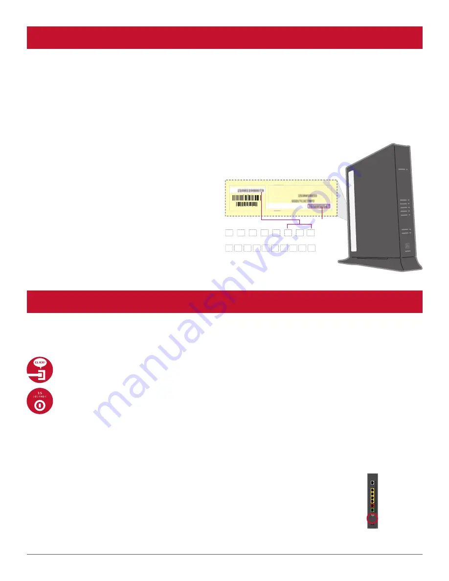
Write down your new Network Name (SSID) and new Wireless Network Key (WPA) to configure a Wi-Fi device. This 
information is on the side of your Wireless Router. The Network Name consists of “2WIRE” and/or “Frontier” plus the last 
three digits of the Wireless Router’s serial number. Be sure to record this information in the form on this page.

Now configure your new wireless network:

1.  Go to your computer’s “Wireless Network Settings” 

and refresh the network list.

2.  Select your Network Name (SSID) from the list. 

You may need to scroll through the list to find your 
SSID.

3.  Enter the ten-digit Wireless Network Key (WPA) in 

the Password field to connect to your network.

4.  Connect all your Wi-Fi devices with the new SSID 

and new Wireless Network Key.

SN: 

For Advanced Configuration:  http://192.168.1.254


System Password: 
Mac Address: 

Wireless Network Key: 

SN:

:

Fo

Sy
M

W

or Adv

ystem

ac A

Wirele

ced Co

Passw
dress:

s Net

an

m P

dd

ess

onfiguration:  http://192.168.1.254

word:

:

twork Key:

:

Network Name (SSID)

Ten-digit Wireless Network Key (WPA) 

WPA

2

W

I

R

E

HAVING TROUBLE?

Many issues can be resolved with these simple steps:

1. Check your connections.

Ensure all cables and cords are connected properly and securely. Cables usually make an audible click when secure.

2a. Check power.

If you have power and the Router is turned on, the Power light on the front of your Wireless Router will have a green 
light. If no lights are on:
1. Ensure the Router is plugged into a working electrical outlet.
2. Ensure power cable on the back of the Router is pushed in firmly.
At this point, your Power light on the front should be green; if not, try another phone outlet and remove any power 
strips.

2b. Power light green; Broadband/Service lights red or blinking.

1.  If after 15 minutes your Broadband/Service light is not green, check that the green cable or 

coaxial cable is connected securely.

2.  If cables are secure, power down the Wireless Router by holding the red-circled reset button 

located on the back of the Router for 15 seconds and wait an additional ten minutes.

Reset button

Summary of Contents for FrontierTV

Page 1: ...SELF INSTALLATION GUIDE...

Page 2: ...d step by step instructions and you ll get hundreds of all digital channels tons of HD channels and thousands of On Demand titles at your fingertips All in crystal clear lifelike clarity This guide wi...

Page 3: ...WIRELESS ROUTER REPLACEMENT...

Page 4: ...ter Unplug the existing Wireless Router and Battery Backup Unit BBU from the electrical outlet Set the BBU aside do not use Refer to Equipment Return and Recycling on page 8 of this guide for recyclin...

Page 5: ...time from the Ethernet yellow ports of the existing Router Connect them to the new Router If you have a cable connected to the Coaxial port of your existing Router disconnect the cable and connect it...

Page 6: ...light may turn orange Wait up to 15 minutes for the indicator lights for Broadband and Service to turn solid green and the Local Ethernet indicator light to start blinking green During this time up t...

Page 7: ...http 192 168 1 254 System Password Mac Address Wireless Network Key SN Fo Sy M W or Adv ystem ac A Wirele ced Co Passw dress s Net an m P dd ess onfiguration http 192 168 1 254 word twork Key Network...

Page 8: ...ns in this guide but my Wireless Router is still not working Reset the Router by pressing and holding the red circled reset button located on the back of the Router for 15 seconds Check all cable conn...

Page 9: ...WIRELESS TV RECEIVER...

Page 10: ...t else do you need Note Additional cable s HDMI RCA Coaxial etc that connect s TV with Wireless Receiver not included POWER Wireless TV Receiver Wireless Access Point Remote control Wireless TV Receiv...

Page 11: ...ow Ethernet cable B Use the power cord to plug the Wireless Access Point into a working electrical outlet A B C The next step is to connect your Wireless Receiver to your TV A Connect the receiver to...

Page 12: ...n the receiver B Press the Wi Fi Protected Setup WPS button on the front of the Wireless Access Point and you ll see a fast blinking LED light up on the unit C When you see a green antenna icon on you...

Page 13: ...Wireless Access Point 3 Give it a minute and then repeat the last two steps on Pair Up New Frontier customers or current customers adding a new receiver will need to program the new remote control Pr...

Page 14: ...ADDING A SECOND WIRELESS TV RECEIVER A Complete the installation of the first TV Receiver B Repeat steps in the instructions for Power Up and Pair Up sections in this guide with the second TV Receive...

Page 15: ...WIRELESS RECEIVER REPLACEMENT...

Page 16: ...ess MENU on your remote control The Menu screen should display on your TV Note If your receiver cannot display the menu skip this section From the Menu screen use the arrows on your remote control to...

Page 17: ...nectors past finger tight Failure to properly tighten this connection will degrade the signal and can cause intermittent or continuous video problems POWER VIDEO IN VIDEO OUT NETWORK USB Video Audio P...

Page 18: ...Continue to use your existing remote control it will work with your new receiver To review programming instructions for your remote control visit frontier com helpcenter Your TV screen should look li...

Page 19: ...me with your order return the receiver you replaced and the old two part power cord as is in the box provided to The UPS Store Find the location nearest you by visiting www theupsstore com or by calli...

Page 20: ...WIRED RECEIVER REPLACEMENT...

Page 21: ...rent screen resolution setting To do this press MENU on your remote control The Menu screen should display on your TV Note If your receiver cannot display the menu skip this section From the Menu scre...

Page 22: ...WALL VIDEO IN TO TV VIDEO OUT POWER L OPTICAL R Pb Pb Y Y USB S VIDEO NETWORK AUDIO DIO OUT VIDEO O OUT TO WALL W W VIDEO IN TO TV VIDEO OUT POWER L Pb Pr Y S VIDEO USB NETWORK AUDIO OUT VIDEO OUT TO...

Page 23: ...ing label that came with your order return the receiver you replaced and the old two part power cord as is in the box provided to The UPS Store Find the location nearest you by visiting www theupsstor...

Reviews: