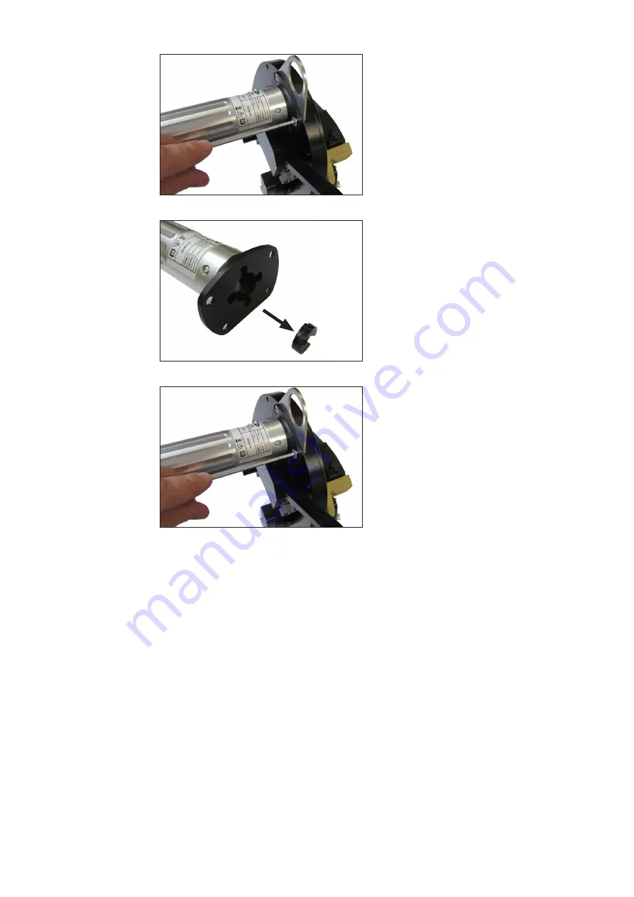
Fronius FOH 10-76 Operating Instructions, Maintenance Download Page 64

64

Replacing the 

plastic coupling

1. Use an Allen key (3 mm) to  

unscrew the retaining bolts of the 

drive motor.

2. Pull the drive motor out of the 

housing.

3. Remove the faulty coupling.
4.  Fit the new coupling to the drive 

motor.

5. Push the drive motor back into the 

housing.

6. Retighten the retaining bolts of the 

drive motor using an Allen key.

4x

Summary of Contents for FOH 10-76

Page 1: ...FOH 8 40 FOH 10 76 FOH 20 114 FOH 40 168 Translated document Operating Instructions Maintenance Open weld head EN Perfect Welding Solar Energy Perfect Charging 42 0426 0234 EN V06 06092018...

Page 2: ......

Page 3: ...tained in them This will prevent faults and incorrect operation or possible damage to installed components Please also obey the safety rules doing so will ensure greater safety when using the product...

Page 4: ...4...

Page 5: ...easures in normal operation 18 Maintenance and repair 18 Safety inspection 19 Disposal 19 Safety labelling 19 Data protection 19 Copyright 19 About this document 20 Function of this document 20 Explan...

Page 6: ...e type of orbital open weld head 52 Welding process 53 Creating a program 53 Starting the welding process 53 After the welding process 55 Removing the open weld head 55 Troubleshooting maintenance and...

Page 7: ...OH 20 114 81 FOH 20 114 82 FOH 40 168 83 Orbital welding torch TTWO 2000 F 86 Wire adjustment unit FOH 86 Wire feeding Orbital TTWO 2000 87 Extension hose pack FCH FOH 10m 87 Motor control cable 88 Tr...

Page 8: ...8...

Page 9: ...9 General information...

Page 10: ...10...

Page 11: ...moved must not be covered pasted or painted over For the location of the safety and danger notices on the device refer to the section headed General remarks in the operating instructions for the devic...

Page 12: ...ed as much with their signatures are trained to produce the required results Checks must be carried out at regular intervals to ensure that operators are working in a safety conscious manner Before us...

Page 13: ...gulation protective goggles with side protection behind the protective visor wear stout footwear that provides insulation even in wet conditions protect the hands with suitable gloves electrically ins...

Page 14: ...or the mains cable to be checked regularly by a qualified electrician to en sure the ground conductor is functioning properly The device must only be operated on a mains supply with a ground conductor...

Page 15: ...e arises despite correct mains connection additional measures are necessary e g use a suitable line filter 2 Welding power leads Keep the power leads as short as possible Allow the power leads to run...

Page 16: ...urce must not be located in such areas Risk of scalding from escaping coolant Switch off cooling unit before disconnecting coolant flow or return lines Observe the information on the coolant safety da...

Page 17: ...ing gas cylinder is not connected leave the valve cap in place on the cylinder The manufacturer s instructions must be observed as well as applicable national and international regulations for shieldi...

Page 18: ...manufacturer s original coolant with other coolants The manufacturer accepts no liability for damage resulting from use of a different coolant In addition all warranty claims will be forfeited The co...

Page 19: ...st be collected separately and returned to an approved recycling facility Be sure to return any device that you no longer require to your dealer or find out about the approved collection and recycling...

Page 20: ...nt knowledge of how to use the device Explanation of safety symbols DANGER Indicates immediate and real danger If it is not avoided death or serious injury will result WARNING Indicates a potentially...

Page 21: ...ividual open weld heads are controlled via the FPA 3020 or FPA 3030 control units The FOH series open weld heads are intended for mobile welding use in the food tech nology general mechanical engineer...

Page 22: ...22...

Page 23: ...23 Safety...

Page 24: ...24...

Page 25: ...e stipulated intervals Keeping a service book with the most important information date operator activities carried out Using the spare parts stipulated by Fronius Using this document in combination wi...

Page 26: ...tions Personal protec tive equipment The operator alone is responsible for the immediate working environment The following safety measures must be put in place and employed Welding goggles Welding shi...

Page 27: ...The manufacturer cannot accept any liability for damage resulting from the use of spare or wearing parts or auxiliary materials that are not approved by the manufacturer Additional overarching policie...

Page 28: ...his can cause severe injury to the eyes Do not look directly into the light beam Use suitable protective goggles or protective shields level of protection 9 15 WARNING Risk of eye injuries due to arc...

Page 29: ...nts The residual heat generated during welding can heat up components to extremely high temperatures Falling components can lead to burns and severe injuries to feet Wear welding footwear when inserti...

Page 30: ...30...

Page 31: ...31 Description of the open weld heads...

Page 32: ...32...

Page 33: ...sories Wearing parts box TTWO 2000 F 48 0100 0041 Extension hosepack FCH FOH 10 m 38 0100 0440 1 FOH open weld head 2 Plug in control line 6 m 3 Transport case with foam insert and removable trolley s...

Page 34: ...34 Accessories continued FOH wire support 58 0913 7000 Balancer spring return 6 10 kg lifting length 2 m 48 0005 1033 Balancer spring return 14 18 kg lifting length 2 m 48 0005 1035...

Page 35: ...eld head 1 Attachment eyelet 2 Head 3 Tool carrier 4 Torch arm 5 Torch holder 6 TIG welding torch 7 Handle with drive unit 8 Clamping system 9 Reducing jaw 10 Fastening screws for reducing jaw 11 Hose...

Page 36: ...eld head 1 2 4 3 1 Control line for the open weld head open weld head end 2 Control line for the open weld head control unit end 3 Combined welding current and shielding gas connection 4 Water cooling...

Page 37: ...weld head and control unit power source 2 Wirefeeder connection cable For controlling the wire exit speed at the open weld head 3 Wirefeed 4 Grounding cable 5 TIG welding torch 6 FRC FPA 3030 remote c...

Page 38: ...eight adjuster and scanner For setting the torch height above the workpiece 3 Angle lock for torch holder For setting the tilt angle of the torch head 4 Knurled screws for lateral adjustment For adjus...

Page 39: ...ntrol cable For suppling and controlling the open weld head 7 Adjusting screw for clamping system For setting the clamping jaws to the respective pipe diameter Controls for open weld head continued Co...

Page 40: ...l position on rigid pipe Possible welding positions PG fixed pipe horizontal welding axis vertical down welding position PF fixed pipe horizontal welding axis vertical up welding position Possible wel...

Page 41: ...41 Commissioning...

Page 42: ...42...

Page 43: ...en the clamping lever and close by to revolution of the adjusting screws Close the clamping lever 4 Release the torch arm Hold the torch arm and pull out the lock for the torch arm NOTE Hold the torch...

Page 44: ...res a constant distance to the pipe is main tained 5 Use the knurled screw on the torch arm to adjust the lateral position in relation to the centre of the pipe 6 Use an Allen key to set the torch hea...

Page 45: ...ng application Positioning the open weld head on the workpiece continued a b Wall thickness a Electrode spacing b 0 5 mm 1 0 mm 0 8 mm 1 25 mm 2 0 mm 1 3 mm 2 25 mm 3 9 mm 1 8 mm With cold wire allowa...

Page 46: ...st the tilt an gle of the holder Once the desired value has been set the fixing screw must be retightened Free length of wire The free length of wire at the wire exit can be adjusted by undoing the fi...

Page 47: ...Switch the main switch on the control unit FPA 3020 FPA 3030 to OFF 2 Disconnect the control unit from the mains by pulling out the mains plug 3 Fold open and release both lock mechanisms on the motor...

Page 48: ...mains by plugging the mains plug back in again 2 Switch the main switch on the control unit FPA 3020 FPA 3030 to ON 3 Press and hold the Thread button on the control unit 4 The welding wire is guided...

Page 49: ...49 Operation...

Page 50: ...50...

Page 51: ...injury from premature arc ignition The arc may be ignited accidentally This can cause serious eye injuries Before operating the open weld head ensure that welding is not switched on by mistake in the...

Page 52: ...Voltage Control Selecting the type of orbital open weld head 1 To select an orbital open weld head call up the Orbital open weld head menu in the main menu of the control system 6 If available select...

Page 53: ...settings menu Detailed information on this can be found in the FPA 3020 Operating Instructions or FPA 3030 Operating Instructions document in the section entitled Parameter settings menu 3 Click the...

Page 54: ...ntinued 5 The open weld head begins to execute the set welding program The hose pack is wound up automatically by the control system s welding program NOTE Ensure that the hose pack is being guided co...

Page 55: ...welding process 1 Pull back the torch arm until the lock engages taking care not to damage the hosepack in the process 2 Open the clamping piece at the quick release lever and remove Removing the ope...

Page 56: ...56...

Page 57: ...57 Troubleshooting maintenance and disposal...

Page 58: ...58...

Page 59: ...place motor control board Replace plastic inter mediate coupling Check welding program Speed is not being regulated Faulty pulse generator Electronic error in the control unit Check pulse generator Re...

Page 60: ...rating instructions for the power source in the section entitled Troubleshooting Errors Cause Remedy Speed is not being regulated Faulty pulse generator Electronic error in the control unit Replace pu...

Page 61: ...cal layperson Someone who is neither a skilled person nor an instructed person The following measures regarding maintenance must be put in place by the system operator a service book containing the re...

Page 62: ...not be used as the basis of any claims whatsoever for defects that arise subsequently 1 Use an Allen key 4 mm to unscrew the retaining bolts of the tool carrier 2 Remove the tool carrier from the head...

Page 63: ...ls and shim rings for damage and replace if necessary 8 Apply new roller bearing grease to the inside of the head 9 Re install all gear wheels in the head 10 Place the cover back on the head and screw...

Page 64: ...the retaining bolts of the drive motor 2 Pull the drive motor out of the housing 3 Remove the faulty coupling 4 Fit the new coupling to the drive motor 5 Push the drive motor back into the housing 6 R...

Page 65: ...65 Technical data...

Page 66: ...66...

Page 67: ...DC Torch type TTWO 2000 F Hosepack length 5 m Welding position PC PF PG Weight without hosepack 3 97 kg 8 75 lbs Power supply 24 V DC Torch type TTWO 2000 F Hosepack length 5 m Welding position PC PF...

Page 68: ...type A B C D E F G max FOH 8 40 90 mm 40 mm 95 mm 7 mm 77 mm 66 mm 120 mm FOH 10 76 142 mm 64 mm 108 mm 5 mm 91 mm 90 mm 230 mm FOH 20 114 200 mm 90 mm 111 mm 7 mm 91 mm 130 mm 260 mm FOH 40 168 300...

Page 69: ...not be held liable for any damage arising from such usage Ambient temperature range during operation 5 C to 40 C 41 F to 104 F during transport and storage 20 C to 55 C 4 F to 131 F Relative humidity...

Page 70: ...70...

Page 71: ...71 Spare parts circuit diagram...

Page 72: ...72...

Page 73: ...from the use of spare or wearing parts or auxiliary materials that are not approved by the manufacturer NOTE Only trained technicians may change parts and may only do so after having read the install...

Page 74: ...FOH 8 40 Art Nr 8 044 201 33 53 61 62 63 54 28 26 27 56 59 60 58 24 57 23 29 55 37 32 6 5 2 1 3 36 34 35 31 4 7 38 40 39 11 18 16 9 51 41 36 44 52 43 49 42 45 46 47 48 50 12 10 19 22 17 14 15 8 20 21...

Page 75: ...2211 Countersunk screw torx M3x20 14 1 48 0005 2093 Threaded spindle 15 2 48 0005 2212 Join pin 16 3 48 0005 2213 Cylinder pin_5m3x20_DIN6325 17 1 48 0005 2094 Link 18 1 48 0005 2095 Clamping lever 19...

Page 76: ...insolator 42 4 48 0005 2236 Thread insert M3x6 43 1 48 0005 2237 Motor Gearbox Encoder Assembly 1 48 0005 2238 Line driver round 44 1 48 0005 2239 Clutch 45 1 48 0005 2107 Motor socket 46 1 48 0005 2...

Page 77: ...76 Art Nr 8 044 202 46 47 48 64 20 65 66 21 8 15 14 17 22 19 10 12 50 45 42 49 43 52 44 36 41 51 9 16 18 13 11 39 40 38 31 35 34 36 3 1 2 5 6 32 37 4 7 33 53 61 62 63 54 55 28 26 27 56 59 60 58 25 24...

Page 78: ...rsunk screw torx M4x12 14 1 48 0005 2112 Threaded spindle 15 2 48 0005 2262 Join pin 16 3 48 0005 2263 Cylinder pin 3m6x20_DIN6325 17 1 48 0005 2113 Link 18 1 48 0005 2114 Clamping lever 19 2 48 0005...

Page 79: ...Connector plug 48 4 48 0005 2241 Cylinder screw M3x6 DIN 912 49 8 48 0005 2242 Lens head screw M3x6 DIN 7380 50 4 48 0005 2243 Countersunk screw M5x12 DIN 7991 51 4 48 0005 2244 Cylinder screw M3x16...

Page 80: ...3 54 28 26 27 56 53 55 59 60 58 25 24 29 57 23 37 32 33 34 36 1 2 3 5 6 7 4 31 35 39 38 40 66 65 64 13 20 21 15 18 8 14 19 16 9 10 12 50 52 44 36 43 41 17 42 49 51 45 46 47 48 11 22 FOH 20 114 Art Nr...

Page 81: ...x M4x20 13 2 48 0005 2210 Countersunk screw torx M4x10 14 1 48 0005 2130 Threaded spindle 15 2 48 0005 2277 Join pin 16 3 48 0005 2278 Cylinder pin 5m6x20_DIN6325 17 1 48 0005 2131 Link 18 1 48 0005 2...

Page 82: ...nector plug 48 4 48 0005 2241 Cylinder screw M3x6 DIN 912 49 8 48 0005 2242 Lens head screw M3x6 DIN 7380 50 4 48 0005 2243 Countersunk screw M5x12 DIN 7991 51 4 48 0005 2244 Cylinder screw M3x16 DIN...

Page 83: ...0 168 Art Nr 8 044 204 54 63 62 61 53 33 28 26 27 5 5 6 5 59 60 58 25 24 23 57 37 32 5 6 2 1 3 36 34 35 31 38 40 39 18 13 16 11 9 51 41 36 44 52 43 49 42 46 47 48 45 50 12 10 19 22 17 14 15 64 20 65 2...

Page 84: ...torx M4x10 14 1 48 0005 2144 Threaded spindle 15 2 48 0005 2290 Join pin d14x15 16 3 48 0005 2278 Cylinder pin 5m6x20_DIN6325 17 1 48 0005 2145 Link 18 1 48 0005 2146 Clamping lever 19 2 48 0005 2214...

Page 85: ...cover 47 1 48 0005 2240 Connector plug 48 4 48 0005 2241 Cylinder screw M3x6 DIN 912 49 8 48 0005 2242 Lens head screw M3x6 DIN 7380 50 4 48 0005 2243 Countersunk screw M5x12 DIN 7991 51 4 48 0005 224...

Page 86: ...86 Wire adjustment unit FOH Orbital welding torch TTWO 2000 F 58 0913 7000...

Page 87: ...87 Wire feeding Orbital TTWO 2000 38 0100 0440 Extension hose pack FCH FOH 10m...

Page 88: ...nsport case FOH 48 0005 2426 Motor control cable Quantity Article number Description 1 1 3 1610FOH Motor control cable FOH 6m 10 pole cable gland on weld head side 14 pin cable connector on controller...

Page 89: ...xiliary materials that are not approved by the manufac turer Wearing parts box TTWO 2000 F Original spare parts Content of wearing parts box 42 0001 1150 48 0100 0041 48 0005 2187 42 0300 7287 42 0300...

Page 90: ...12 5 19x25 5 thread type 42 0300 2857 1 Gas nozzle ceramic 11 16x13 thread type 42 0300 7287 1 Gas nozzle ceramic 19 32x24 thread type 42 0411 4002 2 Tungsten electrode WC20 2 4x175 42 0411 4003 2 Tun...

Page 91: ...XJ 9 B 1 B B1 B3 B1 B3 02725 7RS YLHZ RQ VROGHU FXSV 0 PRWRU UHG PRWRU EODFN HQFRGHU 1 JUD HQFRGHU 9 EURZQ HQFRGHU ZKLWH HQFRGHU EOXH HQFRGHU HOORZ HQFRGHU JUHHQ UHG SXUSOH EUDXQ HOORZ RUDQJH EODFN JU...

Page 92: ...B B1 B3 B1 B3 02725 7RS YLHZ RQ VROGHU FXSV 0 PRWRU UHG PRWRU EODFN HQFRGHU 1 JUD HQFRGHU 9 EURZQ HQFRGHU ZKLWH HQFRGHU EOXH HQFRGHU HOORZ HQFRGHU JUHHQ UHG SXUSOH EURZQ HOORZ RUDQJH EODFN JUH EODFN U...

Page 93: ...UHIHUUHG WR E WKLV HFODUDWLRQ PHHW WKH IROORZLQJ GLUHFWLYHV DQG VWDQGDUG V LUHFWLYH 8 OHFWULFDO SSDUDWXV RZ 9ROWDJH LUHFWLYH LUHFWLYH 8 OHFWURPDJ FRPSDWLELOLW LUHFWLYH 8 5R 6 LUHFWLYH 0DFKLQHU LUHFWL...

Page 94: ...94 FRONIUS INTERNATIONAL GMBH TechSupport Automation www fronius com addresses www fronius com...

Reviews: