background image

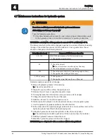
4.7 Maintenance instructions for hydraulic system

WARNING

Do not use unskilled personnel for hydraulic system maintenance
Risk of injury and damage to property!

Take the following precautions:

❒ Only allow trained professionals to carry out servicing and maintenance work

on the hydraulic system. Follow the manufacturer's operating instructions.

NOTICE! Do not allow the oil temperature to 50°C or fall below -30°C.
The interval at which oil should be changed depends on a variety of factors including
the age of the oil and the amount of dirt contained in it. As a general rule, the oil
should be changed at the following intervals:

Interval [service hours]

Component / Maintenance Operation

50 – 100

ONE-TIME maintenance after first commissioning:

❒ Change the oil and the filter


50

❒ Check the oil level

➥ The oil must show no visible signs of foaming

❒ Check the tightness of screw connectors

200

❒ Check the return filter for dirt (pressure gauge on filter)
❒ Change the filter cartridge if necessary

5,000 (or yearly)

❒ Change the oil
❒ Change the return filter and the vent filter sets

Recommended procedure for oil change:

❒ Move all hydraulic cylinders to the end stop

➥ This will expel all the oil

❒ Drain off or pump off the oil from the hydraulic unit
❒ Remove the unit cover or open the inspection cover
❒ Thoroughly clean the oil tank (make sure you remove all oil sludge)
❒ Change the return filter and the vent filter sets
❒ Refit the unit cover or close the inspection cover
❒ Fill the tank with hydraulic oil to the level mark shown on the inspection glass

☞ Use the hydraulic oil grade specified by the manufacturer

❒ At the other end of the cylinder plunger (relative to its current position), remove the

hydraulic cylinder hose fitted to the fixed piping side.

❒ Using the hydraulic unit move the cylinders to the other end position

➥ The remaining old oil will be pushed out of the hose and into the container

❒ Refit the hydraulic hoses and check the seal
❒ Bleed the hydraulic system and check the oil level

NOTICE! Dispose of hydraulic oil in accordance with local regulations!


4

Servicing

Maintenance instructions for hydraulic system

54

Froling GesmbH | A-4710 Grieskirchen, Industriestraße 12 | www.froeling.com

Summary of Contents for Lambdamat LM 1000 SPS

Page 1: ...al German operating instructions for the operator Read and follow the instructions and safety information Technical changes typographical errors and omissions reserved B1300015_en Edition 11 08 2015 F...

Page 2: ...2 8 1 Overheating of the system 21 2 8 2 Smell of flue gas 22 2 8 3 Fire in the system 22 3 Operating the system 23 3 1 Assembly and initial startup 23 3 2 Filling the store space with fuel 24 3 2 1...

Page 3: ...s recirculation FGR duct 45 4 5 5 Checking the heat exchanger 45 4 5 6 Cleaning the area under the moving grate 46 4 6 Periodic inspection and cleaning approx 3 000 hrs 47 4 6 1 Cleaning the combustio...

Page 4: ...s with fault message 57 5 3 1 Procedure for fault messages 58 5 3 2 Acknowledging a fault message 58 6 Appendix 60 6 1 Addresses 60 6 1 1 Address of manufacturer 60 6 1 2 Address of the installer 60 T...

Page 5: ...ronmentally friendly and economical operation of the system The constant further development of our products means that there may be minor differences from the pictures and content If you discover any...

Page 6: ...on chamber door 16 Boiler return connection 6 Burning chamber door 17 Safety valve connection 7 Combustion air blower fan 18 Boiler flow connection 8 Ash container 300l optional 19 Flue gas recirculat...

Page 7: ...25 Secondary air servo motor II 23 Air distribution frame of compressed air cleaner optional 26 Tertiary air servo motor 24 Primary air actuator 27 High limit thermostat STL General 1 Lambdamat LM 10...

Page 8: ...ber 29 Burn back protection system shown here burn back flap optional rotary valve 32 Multiple pass heat exchanger 30 Moving grate 33 Cleaning door 1 General Lambdamat LM 1000 Product Overview 8 Froli...

Page 9: ...re not observed it will lead to serious injury or death You must follow the instructions WARNING The dangerous situation may occur and if measures are not observed it will lead to serious injury or de...

Page 10: ...g instructions Wear safety shoes Always wear protective gloves Wear hearing protection Keep the doors closed Turn off the main switch Unauthorised access prohibited No not walk on the surface Warning...

Page 11: ...spontaneous combustion of carbonisation gases or flash fires which can in turn cause serious accidents When operating the boiler please note the following Instructions and information regarding versi...

Page 12: ...ill then be fully responsible for the declaration of conformity according to the valid guideline s for the product and will need to attach the new CE label to the device This person will then assume a...

Page 13: ...alve The store should be fitted with a pressure release device in accordance with regional regulations The same limits apply for the permitted water content of sawdust as for wood chips NOTICE For fue...

Page 14: ...fined in the Permitted fuels section and particularly the burning of refuse is not permitted CAUTION In case of use of non permitted fuels Burning non permitted fuels increases the cleaning requiremen...

Page 15: ...m and changing or deactivating safety equipment is prohibited Always comply with all fire building and electrical regulations when installing or operating the system in addition to following the opera...

Page 16: ...ken from and expelled directly outside and the openings and air ducts should be designed to prevent weather conditions foliage snowdrifts etc from obstructing the air flow Unless otherwise specified i...

Page 17: ...m with a storage tank as this ensures a continuous supply of fuel in the ideal output range of the boiler For the correct dimensions of the storage tank and the line insulation in accordance with NORM...

Page 18: ...ool down 3 SAFETY OVERLOAD SWITCHES MOTOR PROTECTION SWITCHES RESIDUAL CURRENT PROTECTIVE DEVICES RCD Switch off the related component in the event of fault currents or overloads 4 SAFETY TEMPERATURE...

Page 19: ...tor switch past the 0 position engages the locking lever The switch can be locked with a padlock to prevent it from being switched on again On completion of the maintenance work Remove the padlock Tur...

Page 20: ...ARNING Opening the door to the combustion or burning chamber or the cleaning door or lids during operation may result in injury or damage or flue gas generation Therefore Do not open any doors or lids...

Page 21: ...in the desired mode 2 8 Emergency procedure 2 8 1 Overheating of the system If the system overheats and the safety devices fail proceed as follows NOTICE Do not under any circumstances switch off the...

Page 22: ...ler according to procedure Ventilate the room where the boiler is installed Close the fire door and doors to living areas 2 8 3 Fire in the system DANGER In case of fire in the system Risk of death by...

Page 23: ...lation Installation of water pipes Flue gas connection including all insulation work Work must comply with local fire protection regulations The operator must ensure that at least 50 of the boiler s r...

Page 24: ...The boiler follows the shutdown procedure and switches to Switched off OFF status turn off the boiler s main switch turn off the main switch on the expansion switch cabinet if installed For blowing i...

Page 25: ...mpty the rotary agitator arms spring blades are fully extended If the rotary agitator arms spring blades are covered in this position with a large amount of fuel the weight of the fuel will stop them...

Page 26: ...r s main switch Turn on the main switch on the expansion switch cabinet if installed Switch on the boiler by tapping Boiler on at the mode icon For the highest possible heat consumption the storage ta...

Page 27: ...itator arms are not extended the store can be filled as follows Switch off the boiler by tapping Boiler off at the mode icon and allow to cool for at least two hours Close all openings to the store to...

Page 28: ...hand The head of the rotary agitator should be completely covered Follow the instructions on working in the fuel store NOTICE Refer to the notice supplied with the boiler at the entrance to the store...

Page 29: ...dumping height depending on the fuel density as specified in the operating instructions for the sliding floor must not be exceeded Driving over the fuel in the store can cause the material to be comp...

Page 30: ...s be moved into an upright position in order to fill the store This can be done as follows If the store is filled while the boiler system is running the screw moves automatically into an upright posit...

Page 31: ...d via the controller according to the selected mode in automatic mode For other modes press the relevant function key Information on function keys in the relevant operating instructions for the SPS 40...

Page 32: ...shutdown procedure and switches to Switched off OFF status after the cleaning cycle Turn off the main switch Boiler controller is switched off The components powered via the control cabinet are power...

Page 33: ...tc WARNING Inspection and cleaning work on a system which is operational Risk of serious injuries from automatic startup of the system and severe burns from hot parts and the flue gas pipe When workin...

Page 34: ...he Technical Directive for Fire Prevention TRVB NOTICE As well as the cleaning and maintenance tasks explained in these instructions also refer to the specifications according to TRVB H 118 given in t...

Page 35: ...rge pipe must not drip NOTICE Exception Boiler temperature 100 C If water is dripping from the discharge pipe Clean the discharge safety device in accordance with the manufacturer s instructions or ha...

Page 36: ...nger ID fan Flue gas recirculation FGR Combustion air blower fan Burn back protection system Check function and seal Screw drives Loading and ash removal Door contact switch When the door is opened th...

Page 37: ...OFF status 4 3 1 Emptying the combustion chamber ash container optional NOTICE The current fill level of the ash container can also be checked while the boiler is in operation Important The ash contai...

Page 38: ...ted by the ash screws weighs approx 1kg L At least two people are therefore required to transport the ash container depending on its fill level To replace the ash container 1 Remove the coupling cap S...

Page 39: ...precautions to prevent accidental switching on allow the boiler to cool off for at least 1 hour once all of the tasks have been completed turn the main switch back on and switch the boiler on in the...

Page 40: ...r Cleaning the combustion chamber Open the combustion chamber door Remove unburned material and foreign bodies from the combustion chamber Using a flat scraper move the ash on the combustion chamber g...

Page 41: ...ews in manual mode Ash that gathers is moved into the ash container Empty the ash container whenever necessary 4 3 3 Emptying the multicyclone ash container Check the ash level and empty the container...

Page 42: ...ion air fan page 47 See Checking the underpressure controller page 51 See Checking the seal of the cleaning port doors page 47 See Checking the combustion chamber overpressure sensor page 52 See Check...

Page 43: ...em always wear protective gloves only operate the boiler using the handles provided switch off the boiler by tapping Boiler off at the mode icon The boiler follows the shutdown procedure and switches...

Page 44: ...rew in the broadband probe once more by hand 4 5 3 Cleaning the flue gas temperature sensor Pos C See Periodic inspection and cleaning page 42 Loosen the retaining screw and pull out the flue gas temp...

Page 45: ...acuum 4 5 5 Checking the heat exchanger Pos E See Periodic inspection and cleaning page 42 1 Open the reversing chamber door 2 Check the heat exchanger pipes and if necessary clean thoroughly with a b...

Page 46: ...aning cover Check the moving grate area and ash rakes for dirt and deposits Clean where necessary Check the grate grate shafts and grate bearings for wear and deformation Exchange components wherever...

Page 47: ...ng the seal of the cleaning port doors Pos H See Periodic inspection and cleaning page 42 1 Open the reversing chamber door 2 Check that the fibre glass seal of the cleaning port doors is perfectly al...

Page 48: ...ction and cleaning page 42 The example below of the burning chamber door shows how to check the position and seal The procedure is the same for checking the seal on the combustion chamber door NOTICE...

Page 49: ...hook See Positioning the burning chamber and combustion chamber door page 49 4 6 5 Positioning the burning chamber and combustion chamber door The example below shows how to position the burning cham...

Page 50: ...lly remove the combustion chamber temperature sensor if necessary clean carefully When all tasks have been completed replace the combustion chamber temperature sensor 1 Open the reversing chamber door...

Page 51: ...ls with the flat scraper 7 Check the fireclay elements for wear 8 Remove any ash which has gathered 9 Close all doors again 4 6 7 Checking the underpressure controller Pos L See Periodic inspection an...

Page 52: ...with a fine cloth Check that the spacer tube is clear Insert the combustion chamber excess pressure sensor and fix loosely with fixing screws 4 6 9 Cleaning the FGR blower fan Pos N See Periodic inspe...

Page 53: ...he running wheel and coil of the induced draught fan with a brush 4 6 11 Lubricating the bearings Grease the bearings of the screws and the drives at the correct points 4 6 12 Checking the flue gas pi...

Page 54: ...000 or yearly Change the oil Change the return filter and the vent filter sets Recommended procedure for oil change Move all hydraulic cylinders to the end stop This will expel all the oil Drain off o...

Page 55: ...the course of this maintenance the entire system is inspected and optimised particularly regulation and control of the boiler The emission measurement carried out can also be used to draw conclusions...

Page 56: ...sure that the system is disposed of in an environmentally friendly way in accordance with waste management regulations You can separate and clean recyclable materials and send them to a recycling cent...

Page 57: ...ording to the specified program After a power failure check whether the STL high limit thermostat has tripped Keep the doors of the boiler closed during and after the power failure at least until the...

Page 58: ...the option of resolving the error quickly to prevent a shutdown ERROR ORANGE warning sign Message with ORANGE background The boiler follows the shutdown procedure and remains in Switched off OFF statu...

Page 59: ...is indicated by an arrow symbol 2 Acknowledge the current fault by tapping the check mark 3 A symbol 4 appears once the fault has been acknowledged Once all faults have been fixed and acknowledged al...

Page 60: ...und Beh lterbau GesmbH Industriestra e 12 A 4710 Grieskirchen AUSTRIA TEL 0043 0 7248 606 0 FAX 0043 0 7248 606 600 INTERNET www froeling com 6 1 2 Address of the installer Stamp 6 Appendix Addresses...

Reviews: