


F
riStam
P
umPS
8
c
hecking
aLignment
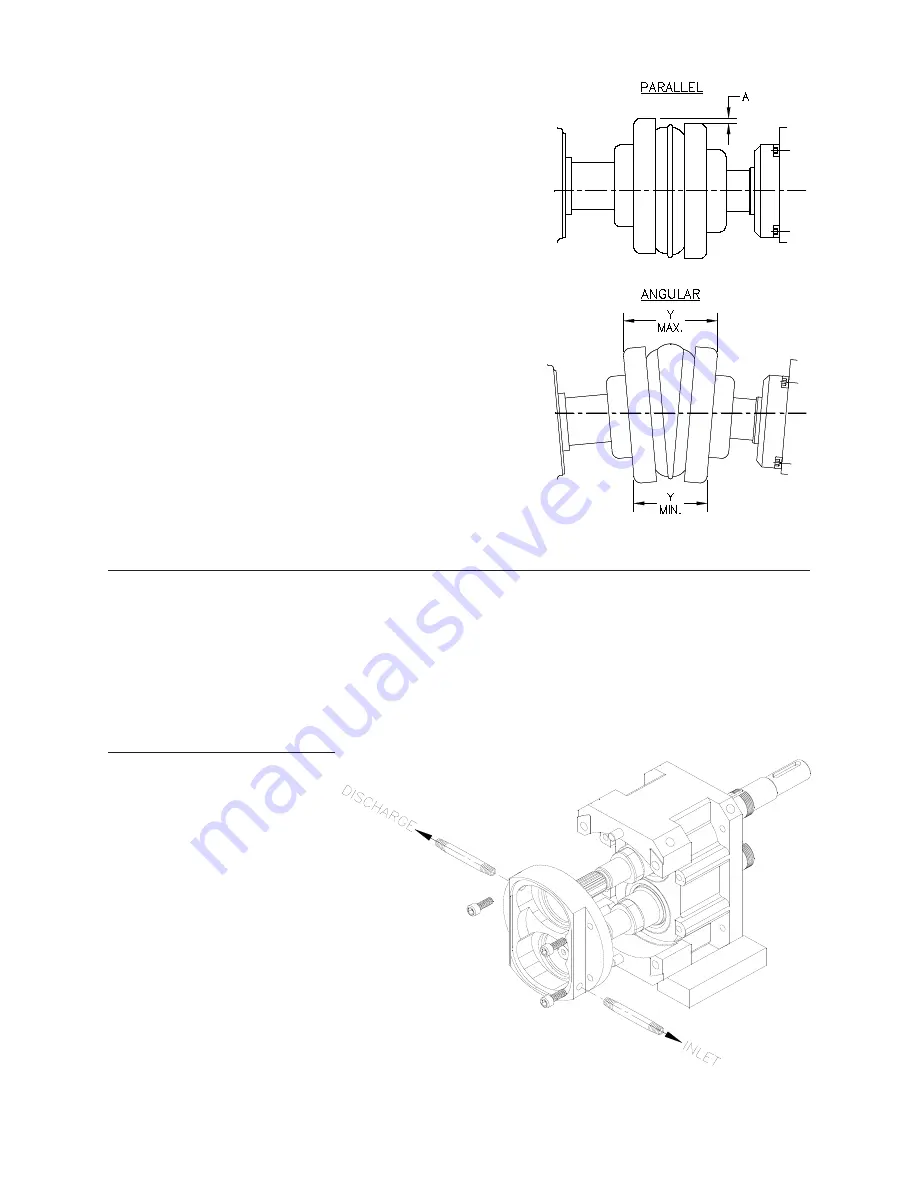
Remove the wire ring from the coupling sleeve and let it
hang between the sleeve and one of the flanges.
To check the parallel alignment place a straight edge
across the two coupling flanges and measure the maxi-
mum offset at various points around the periphery of the
coupling without rotating the coupling. If the maximum
offset exceeds the figure shown under “Parallel” in Table
A1 (page 5), realign the shafts.
Check the angular alignment with a micrometer or cali-
per. Measure from the outside of one flange to the out-
side of the other (“Y”) at intervals around the periphery
of the coupling. Determine the maximum and minimum
dimensions without rotating the coupling. The difference
between the maximum and minimum must not exceed
the figure given under “Angular” in Table A1 (page 5). If
a correction is necessary, be sure to recheck the parallel
alignment.
Replace the wire ring on the O.D. of the coupling sleeve.
e
LectricaL
c
onnectionS
Have an electrician connect the drive motor using sound electrical practices. Ensure that
proper motor overload protection is provided. The size of the drive selected should meet the
requirements of the operating conditions. A change in conditions (for example, higher viscos-
ity product, higher product specific gravity, lower head losses) can overload the motor. For
technical assistance regarding operating condition changes, please contact Fristam Pumps.
Make sure that the pump is rotating in the correct direction.
W
ater
F
LuSh
c
onnectionS
If your pump is equipped
with a double mechanical
seal, water must be supplied
to provide cooling and lubri-
cation. Connect supply and
return lines to the water pipes
supplied with product seal
on your pump. See
Figure 4
for the proper orientation.
Use about 3-12 gallons (11-45
lph) per hour of water at 1-2
psi (0.07 - 0.14 bar). Note:
maximum pressure =
5
psi.
Excessive seal pressure and/or
flow rate through the product
seal cavity may cause increased seal wear and shorten seal life.
Figure 3
Figure 4