7
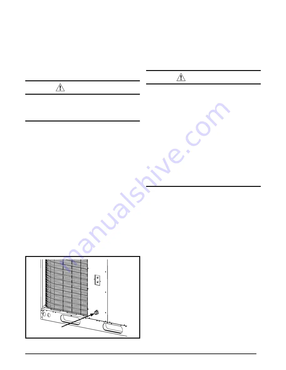
condensate
Drain
Figure 3. condensate Drain location
•
Duct lining must be UL classified batts or blankets with
a fire hazard classification of FHC-25/50 or less.
•
Fiber duct work may be used in place of internal duct
liners if the fiber duct work is in accordance with the
current revision of the SMACNA construction standard
on fibrous glass ducts. Fibrous duct work and internal
acoustical lining must be NFPA Class 1 air ducts when
tested per UL Standard 181 for Class 1 ducts.
air Filter Requirements
waRning:
never operate the unit without a filter in place.
Dust and lint could accumulate on internal parts,
resulting in loss of efficiency, equipment damage
and possible fire.
•
This unit is not supplied with air filter(s) and has no
factory equipped means for accomodating internal
filter(s). A suitable air filter must be installed upstream
of the evaporator coil of the return air system.
•
All return air must pass through the filters before entering
the evaporator coil.
It is important that all filters be
kept clean and replaced frequently to ensure proper
operation of unit. Dirty or clogged filters will reduce the
efficiency of the unit and result in unit shutdowns.
•
Air filter pressure drop must not exceed 0.08 inches WC.
• Downflow Installations require an internal filter
accessory kit to be installed.
• Horizontal Installations require the air filter system be
installed in the return air ductwork.
condensate Drain
Condensate is removed from the unit through the 3/4”
female pipe fitting located on the front side of the unit
(See Figure 3). Install a 2 inch condensate trap in the
drain line of the same size and prime with water. When
connecting rigid drain line, hold the female fitting with a
wrench to prevent twisting. Do not over tighten! Refer
to local codes and restrictions for proper condensate
disposal requirements.
HeaT PumP inSTallaTion
Packaging Removal
Remove the shipping carton and User’s Manual from the
equipment. Take care not to damage the tubing connections
when removing the carton. For rooftop installations, remove
and discard the two supports attached beneath the unit.
Rigging and Hoisting
waRning:
To avoid the risk of property damage, personal
injury, or death, it is the rigger’s responsibility
to ensure that whatever means are used to hoist
the unit are safe and adequate:
•
The lifting equipment must be adequate for the
load. Refer to Table 7 (page 16) for unit weights.
•
The unit must be lifted from the holes in the
base rails using cables or chains.
•
Spreader bars are required to protect the unit
and ensure even loading.
•
keep the unit in an upright position at all times.
The rigging must be located outside the units
center of gravity. Refer to Figure 9 (page 16)
for locating the center of gravity.
•
all panels must be securely in place during
rigging and hoisting.
minimum clearance Requirements
Q4SE units are certified as combination heating and
cooling equipment for outdoor rooftop or ground level
installations. Figure 2 (page 6) displays the minimum
clearances to obstructions for both Downflow and
Horizontal discharge.
Units may be installed on Class A, B, or C roof covering
material when used with bottom supply and return air
ducts as long as the following requirements are met:
• If using vertical supply and return air ducts, a roof curb
must be installed prior to unit installation. See Rigging
and Hoisting section for setting of the unit.
Horizontal to Downflow conversion
The unit is shipped ready for horizontal duct connections.
If down flow ducts are required, the unit must be converted
following the steps below for both the supply and return
ducts.
1. Remove the horizontal duct cap.
2. Locate the duct cap inside the duct openings and
remove the screw holding it in place.
3. Lift the cap out of the unit. (Hint: The cap can be
pushed up from the bottom by reaching through the
fork slot).
4. Cover the horizontal duct opening with the horizontal
duct cap. The insulation will be on the indoor side.
5. Fasten the cover with screws to seal.


