background image

3

ELECTRIC WALL OVEN INSTALLATION INSTRUCTIONS

Important Notes to the Installer

1.  Read all instructions contained in these installation 

instructions before installing the wall oven.

2.  Remove all packing material from the oven 

compartments before connecting the electrical supply 
to the wall oven.

3.  Observe all governing codes and ordinances.
4.  Be sure to leave these instructions with the consumer.
5.  Oven door may be removed to facilitate installation.
6. 

THESE OVENS ARE NOT APPROVED FOR 
STACKABLE OR SIDE-BY-SIDE INSTALLATION.

Important Note to the Consumer

Keep these instructions with your Owner's Guide for 
future reference.

IMPORTANT SAFETY INSTRUCTIONS

 Be sure your wall oven is installed and grounded 

properly by a qualified installer or service 
technician.

• 

This wall oven must be electrically grounded in 
accordance with local codes or, in their absence, 
with the National Electrical Code ANSI/NFPA 
No.70- latest edition in United States, or with CSA 
Standard C22.1, Canadian Electrical Code, Part 1, 
in Canada.

 Stepping, leaning or sitting on the 

door of this wall oven can result in serious injuries 
and can also cause damage to the wall oven.

• 

Never use your wall oven for warming or heating 
the room. 

Prolonged use of the wall oven without 

adequate ventilation can be dangerous.

 The electrical power to the oven must 

be shut off while line connections are being made. 
Failure to do so could result in serious injury or 
death.

1. Carpentry

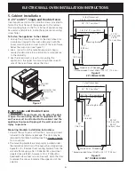
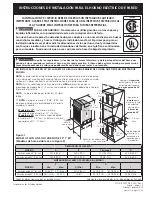
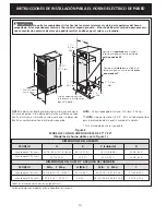
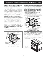
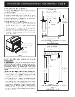
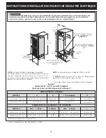
Refer to figure 1 or 2 for the dimensions applicable to 
your appliance, and the space necessary to receive the 
oven. The oven support surface may be solid plywood or 
similar material, however the surface must be level from 
side to side and front to rear.

2. Electrical Requirements

This appliance must be supplied with the proper voltage 
and frequency, and connected to an individual, properly 
grounded branch circuit, protected by a circuit breaker 
or fuse. To know the circuit breaker or fuse required 
by your model, see the serial plate to find the wattage 
consumption and refer to table A to get the circuit 
breaker or fuse amperage.

Observe all governing codes and local ordinances

1. A 3-wire or 4-wire single phase 120/240 or 120/208 

Volt, 60 Hz AC only electrical supply is required on a 

separate circuit fused on both sides of the line (red 

and black wires). A time-delay fuse or circuit breaker is 

recommended. DO NOT fuse neutral (white wire). Only 

certain cooktop models may be installed over certain 

built-in electric oven models. Approved cooktops and 

built-in ovens are listed by the MFG ID number (see the 

insert sheet included in the literature package).

NOTE:

 Wire sizes and connections must conform with 

the fuse size and rating of the appliance in accordance 

with the American National Electrical Code ANSI/NFPA 

No. 70-latest edition, or with Canadian CSA Standard 

C22.1, Canadian Electrical Code, Part 1, and local codes 

and ordinances.

  An extension cord should not be used 

with this appliance. Such use may result in a fire, 

electrical shock, or other personal injury. 

If you need 

a longer power cord you can purchase a 10' (3 m) power 

cord kit #903056-9010 by calling the Service Center

.

2.  These appliances should be connected to the fused 

disconnect (or circuit breaker) box through flexible 

armored or nonmetallic sheathed cable. The flexible 

armored cable extending from the appliance should 

be connected directly to the junction box. The 

junction box should be located as shown in Figure 

1 or Figure 2 and with as much slack as possible 

remaining in the cable between the box and the 

appliance, so it can be moved if servicing is ever 

necessary.

3.  A suitable strain relief must be provided to attach 

the flexible armored cable to the junction box.

Table A

Appliance 

Rating Watts

240V

Protection 

Circuit 

Recommended

Appliance 

Rating Watts

208V

Protection 

Circuit 

Recommended

Less than 4800W

20A

Less than 4100W

20A

4800W - 7200W

30A

4100W - 6200W

30A

7200W - 9600W

40A

6200W - 8300W

40A

9600W and +

50A

8300W and +

50A

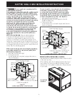
Electrical Shock Hazard

•  Electrical ground is required on this appliance.
•  Do not connect to the electrical supply until appliance 

is permanently grounded.

•  Disconnect power to the junction box before making 

the electrical connection.

•  This appliance must be connected to a grounded, 

metallic, permanent wiring system, or a grounding 
connector should be connected to the grounding 

terminal or wire lead on the appliance.

•  Do not use a gas supply line for grounding the appliance.

Failure to do any of the above could result in a fire, 

personal injury or electrical shock.

Summary of Contents for FEB24S2AB - 24" Electric Wall Oven

Page 1: ...ess heat buildup that may result in heat damage or fire Some models are not available in Canada DO NOT INSTALL A 24 WALL OVEN IN A BASE CABINET WITH A COUNTERTOP ABOVE IT NOTE Dimension G is critical to the proper installation of the built in oven If the oven decorative trim ventilation does not but against the cabinet or if noise is heard on convection models verify dimension G to assure it is ac...

Page 2: ...must be capable of supporting 300 pounds 136 kg NOTE Allow at least 19 3 8 49 2cm clearance for door depth when it is open Dimensions for stainless steel models 3 7 6cm Max 1 1 2 3 8cm Min A D B C I 11 1 2 29 2cm G F H 47 3 4 121 3cm Door Open see note 2 5 1cm Min Hole for cable and electrical junction box on left side for 30 Wall Ovens Electrical Junction Box Right or left side depending of model...

Page 3: ...ase 120 240 or 120 208 Volt 60 Hz AC only electrical supply is required on a separate circuit fused on both sides of the line red and black wires A time delay fuse or circuit breaker is recommended DO NOT fuse neutral white wire Only certain cooktop models may be installed over certain built in electric oven models Approved cooktops and built in ovens are listed by the MFG ID number see the insert...

Page 4: ...nsion panel some models only Oven height can be adjusted with 2 5cm wide wood shims when needed to fit into an existing cabinet cutout opening when cutout height exceeds H Min dimension see Figure 1 or 2 4 Electrical connection It is the responsibility and obligation of the consumer to contact a qualified installer to assure that the electrical installation is adequate and is in conformance with t...

Page 5: ...ne Where local codes permit connecting the appliance grounding conductor to the neutral white wire US Only see figure 5 1 Disconnect the power supply 2 In the junction box connect appliance and power supply cable wires as shown in Figure 5 If oven is used in a new branch circuit installation 1996 NEC mobile home recreational vehicle or where local codes do not permit grounding through the neutral ...

Page 6: ...m Min 29 5 8 75 2 cm Max Mounting Brackets 22 55 9 cm 21 1 4 54 0 cm Wood Shims If Needed 27 1 4 71 8 cm Min 28 7 8 73 3 cm Max B 30 Single and Double Ovens The wall oven can tip when the door is open The mounting brackets supplied with the wall oven must be attached to the cabinet and the appliance to prevent tipping of the wall oven and injury to persons Mounting Brackets Installation Instructio...

Page 7: ...anels are necessary to isolate the unit from adjoining cabinets 36 Min 91 4 cm G F H Use 3 4 1 9 cm plywood installed on two runners flush with toe plate Must be capable of supporting 150 pounds 68 kg Cut an opening in wood base minimum 9 x 9 23 x 23 cm 2 5 cm from left side filler panel to route armored cable to the wall outlet or junction box 4 1 2 11 4 cm Max CUTOUT DIMENSIONS F WIDTH G DEPTH H...

Page 8: ... some models and Clean functions Bake After setting the oven to 350 F 177 C for baking the lower element in the oven should become red Broil When the oven is set to BROIL the upper element in the oven should become red Clean When the oven is set for a self cleaning cycle the upper element should become red during the preheat portion of the cycle After reaching the self cleaning temperature the low...

Page 9: ...erales o y de la parte posterior del horno em potrado Estos espaciadores centran el horno en el espacio provisto El horno debe estar centrado para prevenir una concentración excesiva de calor que podría resultar en daños por el calor o un incendio NO INSTALE ESTE HORNO 24 EN LA PARTE DE ABAJO DE UN ARMARIO DE COCINA QUE TIENE UN MOSTRADOR ENCIMA NOTA La dimensión G está primordial para instalar co...

Page 10: ... el horno en el espacio provisto El horno debe estar centrado para prevenir una concentración excesiva de calor que podría resultar en daños por el calor o un incendio 3 7 6 cm Max 1 1 2 3 8 cm Min A D B C I 11 1 2 29 2 cm G F H 47 3 4 121 3 cm Puerta Abierta vea la nota 2 5 1 cm Min Agujero a la izquierda para el cable y la caja de empalme eléctrica para hor nos de pared de 30 Agujero a la derech...

Page 11: ...monofásico 120 240 o 120 208 voltios 60 hertzios es la única fuente eléctrica que requiere en un circuito separado en ambos lados de la línea alambre negro y alambre rojo se recomienda un fusible o un interruptor de retraso de tiempo No funda a cable neutro alambre blanco Se debe de tener precaución al combinar un horno de pared y una cubierta refiérase a la placa de seria de cada uno de los apara...

Page 12: ...tura exceda la H Min dimensión vea la figura 1 o 2 4 Conexión eléctrica El usuario tiene la responsabilidad personal y obligación de utilizar un instalador calificado para asegurar que la instalación eléctrica está hacha de forma adecuada y está conforme con el Código Eléctrico Nacional ANSI NFPA No 70 última edición en los Estados Unidos o el Código Eléctrico Canadiense CSA Standard C22 1 Part 1 ...

Page 13: ...l aparato y los cables residenciales como se muestra en la figura 5 Si el horno se usa en una instalación de circuito de ramal nuevo 1996 NEC en una casa rodante en un vehículo para recreación o si los códigos locales NO permiten la conexión a tierra a través del cable neutral blanco el armazón del electrodoméstico NO TIENE QUE estar conectado al alambre neutro del sistema eléctrico de 4 alambres ...

Page 14: ...73 7 cm Max 28 1 16 71 3 cm Min 29 5 8 75 2 cm Max Soportes de montaje 22 55 9 cm 21 1 4 54 0 cm 28 1 4 71 8 cm Min 28 7 8 73 3 cm Max Planchitas de madera si sea necesario El largo de hueco recomendado es de 28 1 2 72 4 cm Figura 9 HORNO DOBLE DE 30 Dimensiones del hueco 28 1 2 72 4 cm Min 29 73 7 cm Max 28 1 16 71 3 cm Min 29 7 16 74 8 cm Max Soportes de montaje 42 3 4 108 6 cm 42 106 7 cm 49 1 ...

Page 15: ...or para poder encaminar al cable a la caja de fusibles 4 1 2 11 4 cm Max Para reducir el riesgo de daños personales y de que vuelque el horno a pared el horno debe fijarse a los gabinetes con unas ménsulas de montaje correctamente instaladas 4 Saque el horno aproximadamente 1 pie 30 5 cm fuera del pared posterior del armario Coloque cada fijación sobre el armario y perfore orificios pilotos de 1 1...

Page 16: ...177 C para hornear el elemento de la parte de abajo del horno se debe de ponerse rojo Asar Cuando se pone el horno para asar el elemento de arriba del horno debe de ponerse rojo Limpieza Cuando el horno se pone en el ciclo para que se limpia a si mismo el elemento de arriba debe de ponerse rojo durante la parte de pre calentamiento del ciclo de limpieza Después de que llegue a la temperatura adecu...

Page 17: ... bonne installation du four Si la moulure inférieure ventilation du four ne s adapte pas contre l armoire ou si un bruit se fait entendre sur les modèles à convection vérifiez la dimension G pour s assurer qu elle est correcte Certains modèles ne sont pas disponibles au Canada NOTE Pour un découpage d une hauteur supérieure à la dimension H Min ajoutez une cale de bois d une largeur de 2 5 cm de c...

Page 18: ... en pouces cm NOTE La base doit pouvoir supporter 300lbs 136 kg NOTE Allouez au moins 19 3 8 49 2 cm d espace pour permettre l ouverture de la porte du four Cette dimension est pour le modèle en acier inoxydable 3 7 6cm Max 1 1 2 3 8 cm Min A D B C I 11 1 2 29 2cm G F H 47 3 4 121 3cm Porte ouverte voir la note Boîte de jonction à droite ou à gauche dépendant du modèle 2 5 1cm Min Trou pour le câb...

Page 19: ...sible Observez tous les règlements et les codes locaux applicables 1 Un câble électrique à 3 ou 4 fils de 120 240 ou 120 208 Volt monophasé 60 Hz CA est requis sur un circuit séparé muni d un fusible sur chaque fil conducteur fusible temporisé ou disjoncteur recommandé NE RELIEZ PAS de fusible au neutre Il faut tenir compte de l ajout d une plaque de cuisson superposée au four encastré Référez vou...

Page 20: ...installateur qualifié pour s assurer que l installation électrique est adéquate et conforme avec le National Electrical Code ANSI NFPA No 70 dernière édition ou avec la norme ACNOR C22 1 partie 1 du code canadien de l électricité et les codes et règlements locaux Risque de choc électrique Si cet avertissement n est pas pris en considération un choc électrique ou des blessures sérieuses peuvent sur...

Page 21: ... en cuivre de mise à la terre du câble d alimentation de l appareil 3 Dans la boîte de jonction Raccordez les fils de l appareil à ceux du circuit électrique tel que montré à la figure 6 Emplacement de la plaque signalétique 5 Installation dans l armoire A Fours 24 à cavité simple et fours 27 à cavité simple et à cavité double Insérez l appareil dans son habitacle Les vis servent à attacher le dev...

Page 22: ...n des supports de fixation 1 Déballez le four encastré et trouvez les 2 vis de fixation comprises dans l emballage contenant la littérature Les portes peuvent être enlevées pour faciliter la manipulation du four voir le Guide de l utilisateur pour les instructions 2 Les supports de fixation sont installés sous les moulures latérales décoratives du four pour l expédition voir figure 8 ou 9 À l aide...

Page 23: ... 2 5 cm du panneau latéral gauche pour permettre le passage du câble gainé vers la prise murale ou boîte de jonction 4 1 2 11 4 cm Max DIMENSIONS DE DÉCOUPAGE F LARGEUR G PROFONDEUR H HAUTEUR 30 76 2 cm Four encastré 28 1 2 72 4 cm Min 29 73 7 cm Max 24 61 cm Min 28 1 4 71 8 cm Min 28 7 8 73 3 cm Max 4 Tirez le four d approximativement 1 pied 30 5 cm du mur arrière de l armoire Positionnez chaque ...

Page 24: ...et Nettoyage du four Cuisson au four Après le réglage à 177 C 350 F pour la cuisson au four l élément inférieur du four doit devenir rouge Grillage Lorsque GRILL est sélectionné l élément supérieur du four doit devenir rouge Nettoyage Lorsque le cycle autonettoyant est sélectionné l élément supérieur doit devenir rouge pendant la phase de pré chauffement du cycle Après avoir atteint la température...

Reviews: