Section 4 Component Teardown
4-18
Combustion Tube Removal ( All Gas Models)
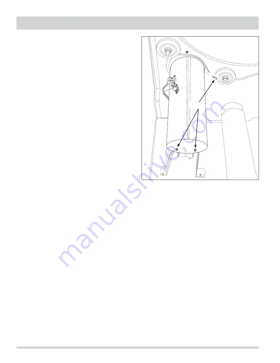
The combustion tube is secured to a mounting bracket in
the front and secured with two screws. The rear of the
combustion tube slides into the heat duct and is secured
with a screw to the right rear of the combustion tube.
To remove the combustion tube:
1. Remove the top panel, rear panel, console, front
panel, front inner panel and drum.
2. Remove burner and gas valve assembly.
3. Disconnect the safety and thermal limiters from wire
harness.
4. Using a #2 square bit screwdriver, extract the two
screws at the front of the combustion tube and the
single screw at the right rear. (See Figure 4-46)
5. Pull the combustion tube from heat duct.
Figure 4-46.
Screws
Summary of Contents for Designer Series
Page 2: ......
Page 87: ...Section 6 Wiring Diagrams 6 1 Affinity Series With Electric Heater ...
Page 88: ...Section 6 Wiring Diagrams 6 2 Affinity Series With Gas Heater ...
Page 89: ...Section 6 Wiring Diagrams 6 3 Gallery Series With Electric Heater ...
Page 90: ...Section 6 Wiring Diagrams 6 4 Gallery Series With Gas Heater ...


