Section 4 Component Teardown
4-8
Front Panel Removal (All Models)
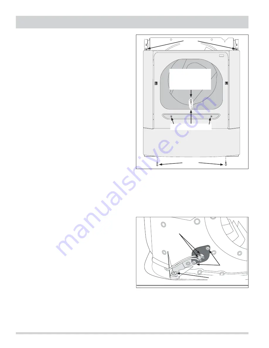
The front panel is secured with four screws, two screws
at each top corner and two along the bottom flange.
Two guide clips mounted to the inner edge of the front
panel slide into slots cut in the cabinet frame.
To remove the front panel:
1. Remove the door assembly and air duct cover.
2. Remove top panel and console, then disconnect door
switch wire leads from drum light and wire harness.
3. Using a #2 square bit screwdriver, extract the top
screw from the front air duct that is visible once the
air duct cover is removed. (See Figure 4-21)
4. Using a #2 square bit screwdriver, extract the two
screws from the bottom of the front panel, then the
two screws at the top of the front panel.
(See Figure 4-21)
5. Lift the front panel upwards then pull away from the
cabinet frame.
Front Air Duct Removal (All Models)
The front air duct is secured with two screws that pass
through the inner front panel and fasten into the front
air duct.
To remove the front air duct:
1. Remove the front panel.
2. From the front of the front panel, use a #2 square
bit screwdriver and extract the two screws securing
the front air duct to the inside of the front panel.
(See Figure 4-21)
Outlet (Exhaust) Thermistor Removal
(All Models)
The outlet thermistor is mounted with a screw to the
front of the exhaust side of the blower outlet ducting.
To remove the outlet thermistor:
1. Remove the top panel, rear panel, console,
front panel, front inner panel and drum.
2. Disconnect the wire leads from the outlet
thermistor terminals.
3. Using a #2 square bit screwdriver, extract the
two screws securing the outlet thermistor to the
blower outlet duct. (See Figure 4-22) To remove
the grounding clip, extract the screw securing the
blower assembly to the unit base.
Figure 4-22.
Figure 4-21. Gallery Series Shown
Screws
Screws
Screws
Blower Assy. Screw
Front Air Duct Screws
Electrical Connections
This Screw Must Be
Removed First To
Remove The Front
Panel
Summary of Contents for Designer Series
Page 2: ......
Page 87: ...Section 6 Wiring Diagrams 6 1 Affinity Series With Electric Heater ...
Page 88: ...Section 6 Wiring Diagrams 6 2 Affinity Series With Gas Heater ...
Page 89: ...Section 6 Wiring Diagrams 6 3 Gallery Series With Electric Heater ...
Page 90: ...Section 6 Wiring Diagrams 6 4 Gallery Series With Gas Heater ...


