


Section 4 Component Teardown
4-11
Stop Switch (Door Sensing Switch),
Primary Interlock Switch, Third Door
Switch And Monitor Switch Removal
Removal
1. Disconnect the power supply cord and remove the
oven from wall and remove outer case. (Refer to
procedure of “Removal of Oven from Wall” and
“Outer case Removal”)
2. Open the door and block it open.
3. Discharge high voltage capacitor.
4. Remove the control panel assembly, referring to
the procedure of “CONTROL PANEL ASSEMBLY,
CONTROL UNIT AND KEY UNIT REMOVAL”.
5. Remove the two (2) screws holding the latch hook to
the oven cavity front flange.
6. Remove latch hook from oven cavity front flange.
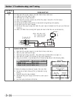
7. Disconnect the wire leads of each switch.
8. Remove each switch from the latch hook by pushing
the one (1) stopper tub holding each switch.
9. Now, each switch is free.
Reinstall
1. Re-install each switch in its place. The primary
interlock switch is in the lower position, door sensing
switch is in the upper position, the third door switch
is in the upper vertical position and the monitor
switch is in the middle position.
2. Re-connect wire leads to each switch. Refer to
pictorial diagram.
3. Secure the latch hook (with two (2) mounting
screws) to oven cavity front flange.
4. Make sure that the monitor switch is operating
properly and check continuity of the monitor circuit.
Refer to chapter “Test Procedure” and “Adjustment
procedure”.
Stop Switch (Door Sensing Switch),
Primary Interlock Switch, Third Door
Switch And Monitor Switch Adjustment
1. Disconnect the power supply cord and remove the
oven from wall and remove outer case. (Refer to
procedure of “Removal of Oven from Wall” and
“Outer case Removal”)
2. Open the door and block it open.
3. Discharge high voltage capacitor.
4. Remove the control panel assembly, referring to
the procedure of “CONTROL PANEL ASSEMBLY,
CONTROL UNIT AND KEY UNIT REMOVAL”.
If door sensing switch, primary interlock switch and
monitor switch do not operate properly due to a
misadjustment, the following adjustment should be
made.
5. Loosen the two (2) screws holding latch hook to the
oven cavity front flange.
6. With door closed, adjust latch hook by moving it
back and forth, and up and down. In and out play
of the door allowed by the upper and lower position
of the latch hook should be less than 0.5mm. The
vertical position of the latch hook should be adjusted
so that the door sensing switch, primary interlock
switch are activated with the door closed. The
horizontal position of the latch hook should be
adjusted so that the monitor switch and third door
switch are activated with the door closed.
7. Secure the screws with washers firmly.
8. Check all of the switches operation. If any switch
has not activated with the door closed, loosen screw
and adjust the latch hook position.
To discharge the high voltage capacitor, wait for 60
seconds and then short-circuit the connection of the
high-voltage capacitor (that is the connecting lead of
the high-voltage rectifier) against the chassis with the
use of an insulated screwdriver.
NOTE
To discharge the high voltage capacitor, wait for 60
seconds and then short-circuit the connection of the
high-voltage capacitor (that is the connecting lead of
the high-voltage rectifier) against the chassis with the
use of an insulated screwdriver.
NOTE
Summary of Contents for CGMV173KB
Page 2: ......
Page 14: ...Section 2 Operation 2 2 Figure 2 1 Oven Off Condition Figure 2 2 Oven ON Cooking Condition ...
Page 51: ...Section 5 Wiring Diagrams 5 1 Wiring Schematic Oven ON Condition ...
Page 52: ...Section 5 Wiring Diagrams 5 2 Pictorial Component Diagram ...
Page 54: ...Section 5 Wiring Diagrams 5 4 LD1 LD2 LD3 LD4 LD5 Control Board ...


