


Section 3 Troubleshooting and Testing
3-9
Procedure
Letter
L
Component Test
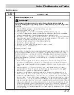
TOUCH CONTROL PANEL ASSEMBLY TEST
The touch control panel consists of circuits including semiconductors such as LSI, ICs, etc.
Therefore, unlike conventional microwave ovens, proper maintenance cannot be performed with only
a voltmeter and ohmmeter. In this service manual, the touch control panel assembly is divided into
two units, Control Unit and Key Unit, and troubleshooting by unit replacement is described
according to the symptoms indicated.
Before testing,
1. Disconnect power supply cord, and remove outer case.
2. Open the door and block it open.
3. Discharge high voltage capacitor. (See Warnings and Instructions on page 3-1)
4. Disconnect the leads to the primary of the power transformer.
5. Ensure that these leads remain isolated from other components and oven chassis by using
insulation tape.
6. After that procedure, re-connect the power supply cord.
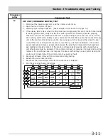
KEY UNIT (Membrane Switch)
1. Disconnect the power supply cord, and then remove outer case.
2. Open the door and block it open.
3. Discharge high voltage capacitor.
4. Check key unit ribbon connection before replacement.
5. Reconnect all leads removed from components during testing.
6. Re-install the outer case (cabinet).
7. Reconnect the power supply cord after the outer case is installed.
8. Run the oven and check all functions.
The following symptoms indicate a defective key unit.
a) When touching the pads, a certain pad produces no signal at all.
b) When touching a number pad, two figures or more are displayed.
c) When touching the pads, sometimes a pad produces no signal.
If the key unit is defective.
1. Disconnect the power supply cord and then remove outer case.
2. Open the door and block it open.
3. Discharge high voltage capacitor.
4. Replace the key unit (membrane switch).
5. Reconnect all leads removed from components during testing.
6. Re-install the outer case (cabinet).
7. Reconnect the power supply cord after the outer case is installed.
8. Run the oven and check all functions.
Summary of Contents for CGMV173KB
Page 2: ......
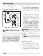
Page 14: ...Section 2 Operation 2 2 Figure 2 1 Oven Off Condition Figure 2 2 Oven ON Cooking Condition ...
Page 51: ...Section 5 Wiring Diagrams 5 1 Wiring Schematic Oven ON Condition ...
Page 52: ...Section 5 Wiring Diagrams 5 2 Pictorial Component Diagram ...
Page 54: ...Section 5 Wiring Diagrams 5 4 LD1 LD2 LD3 LD4 LD5 Control Board ...


