


Section 3 Troubleshooting and Testing
3-16
Procedure
Letter
P
Q
Component Test
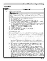
10. Disconnect the power supply cord, and then remove outer case.
11. Open the door and block it open.
12. Discharge high voltage capacitor.
13. Disconnect the dummy resistor circuit from the sensor connector of control panel.
14. Carry out necessary repair.
15. Reconnect all leads removed from components during testing and repairing.
16. Re-install the outer case (cabinet).
17. Reconnect the power supply cord after the outer case is installed. Run the oven and check all
functions.
18. Carry out “Water load cooking test” again and ensure that the oven works properly.
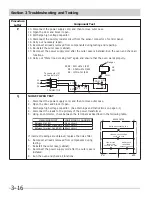
NOISE FILTER TEST
1. Disconnect the power supply cord, and then remove outer case.
2. Open the door and block it open.
3. Discharge high voltage capacitor. (See Warnings and Instructions on page 3-1)
4. Disconnect the leads to the primary of the power transformer.
5. Using an ohmmeter, check between the terminals as described in the following table.
If incorrect readings are obtained, replace the noise filter.
6. Reconnect all leads removed from components during
testing.
7. Reinstall the outer case (cabinet).
8. Reconnect the power supply cord after the outer case is
installed.
9. Run the oven and check all functions.
MEASURING POINT
INDICATION OF OHMMETER
Between N and H
Open circuit.
Between terminal N and GRY
Short circuit.
Between terminal L and RED
Short circuit.
R1,R2: 22Ω ±1% 1/2W
R3: 4.3kΩ ±5% 1/4W
R4: 1MΩ ±% 1/4W
P lunger
NC
NO
C OM
C OM
NO
NC
R 3
R 4
R 1
R 2
1
2
3
F-1
F-2
F-3
To connector (F)
on C ontrol Unit.
C ONNE C TOR
NOISE FILTER
NOISE SUPPRESSION COIL
LINE C R OS S CAPACITOR
0.22μF / AC 250V
LINE BYP AS S
CAPACITOR
0.0033μF / AC 250V
LINE BYP AS S
CAPACITOR
0.0033μF / AC 250V
H
R E D
G R Y
N
Summary of Contents for CGMV173KB
Page 2: ......
Page 14: ...Section 2 Operation 2 2 Figure 2 1 Oven Off Condition Figure 2 2 Oven ON Cooking Condition ...
Page 51: ...Section 5 Wiring Diagrams 5 1 Wiring Schematic Oven ON Condition ...
Page 52: ...Section 5 Wiring Diagrams 5 2 Pictorial Component Diagram ...
Page 54: ...Section 5 Wiring Diagrams 5 4 LD1 LD2 LD3 LD4 LD5 Control Board ...


