page
8
page
9
Installation Steps
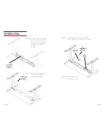
Step 11:
Secure the side bracket to the
worksurface with
M
8 truss
head screws M5*20mm.
M
TRUSS HEAD
SCREWS
M5*20mm
M
TRUSS HEAD
SCREWS
M5*20mm
Step 13:
Insert the
F
control box
in-between crossbeam.
Step 12:
Secure the
E
control panel in the desired
location with
M
2 truss head screws M5*20mm.
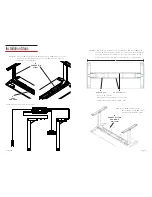
Step 10:
Ensure the leg assembly is still
centered, both side-to-side and
front-to-back. Secure the leg
assembly to the worksurface
with
M
8 truss head screws
M5*20mm.
M
TRUSS HEAD
SCREWS
M5*20mm
F
CONTROL
BOX
E
CONTROL
PANEL


