WAVEPRO
®
WP201-100
Thank you for purchasing the WAVEPRO WP201 Access Point.
This
Quick Start Guide
provides procedures for the initial setup of the WP201-
100.
Note
: For detailed information about network functionality and deployment
scenarios, download the WP201
User Manual
from
WP201-100 Included Equipment
Included Equipment
Qty
Description
Image
Letter
1
WP201-100 Quick Start Guide
1
WP201-100 Access Point
1
Mounting Bracket
A
2
Green / Yellow #10AWG Ground Cables
B
1
Pole Mounting Bracket
C
1
Universal Power Adapter
D
2
Band Clamps
E
1
PoE+ Injector
F
1
Packaged Ground Screw
G
3
7dBi 5GHz omni-directional antennas
H
3
5dBi 2.4GHz omni-directional antennas
H
1
Mounting Kit Package (includes screws, masonry
wedge anchor bolts)
I
Note
: For additional equipment, see
Available Accessories
in the WP201
User Manual.
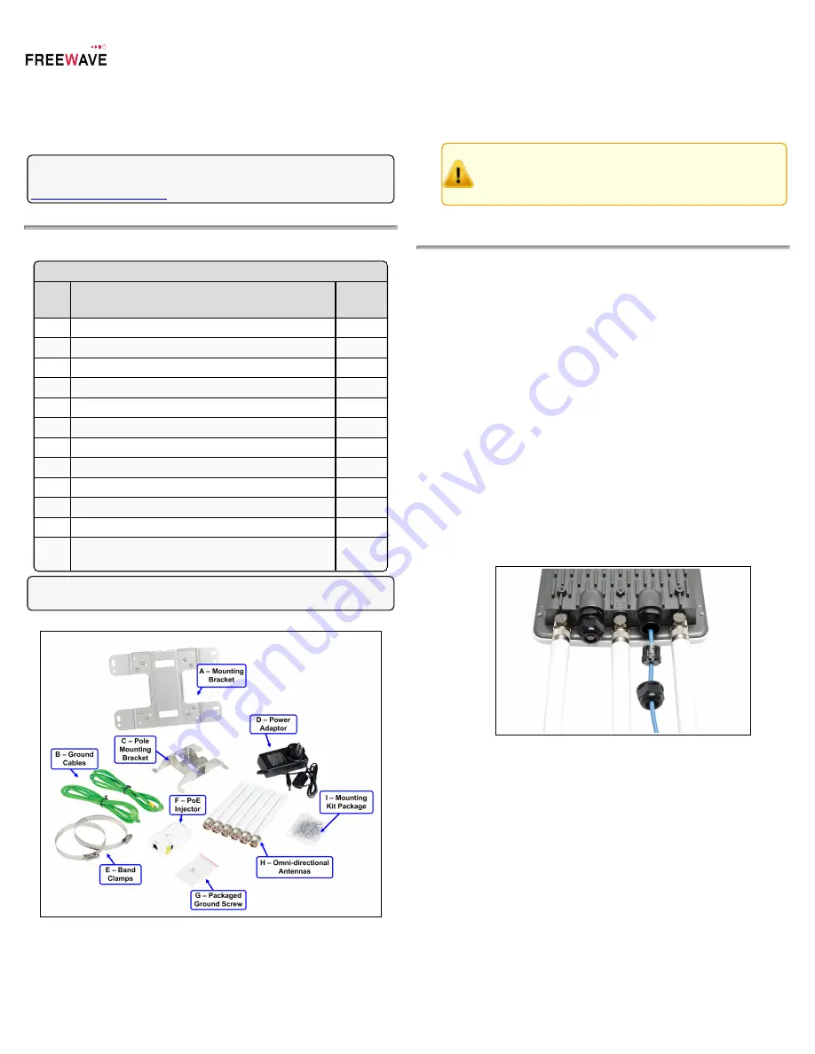
Figure 1: WP201 Included Equipment
User-supplied Equipment
l
Computer with:
l
an Ethernet port.
l
Windows® 7 or greater.
l
Internet Browser: Chrome®, Firefox®, Internet Explorer®, Opera®,
Safari®.
Caution
: The default browser in Windows® 10 is Microsoft®
Edge
. The WP201-100 software does NOT automatically
download to the computer using
Edge
. Use one of the other
identified browsers instead.
l
Qty-2: CAT5e / CAT6 Ethernet cables WITHOUT strain relief
l
Broadband Internet Service (Cable or DSL Modem)
Connect to the WP201-100 Access Point
Power Notes
l
The
Universal Power Adapter
operates from voltages 100 to 240VAC,
50-60Hz.
l
The WP201-100 is powered through the
E1 Port (PoE Input)
by any PSE
(Power Sourcing Equipment) which supports IEEE 802.3at (PoE+)
including the provided
PoE+ Injector
.
Procedure
1.
Remove the protective caps from the antenna ports.
2.
Attach using a strong hand-tighten the 2.4GHz and 5GHz antennas to their
same-labeled antenna ports on the WP201-100.
3.
If applicable, replace the protective caps on unused antenna ports.
4.
Remove the compression gland assembly from the
E1 Port (PoE Input)
.
5.
Thread one end of the Ethernet cable through the cap of the compression
gland.
6.
Insert the compression gland onto the Ethernet cable.
7.
Connect the assembled Ethernet cable (WITHOUT strain-relief) to the
E1
Port (PoE Input)
of the WP201-100 and the other end into the
AP/Bridge
port on the
PoE+ Injector
.
Figure 2: Compression Gland on the CAT5e / CAT6 Ethernet
cable attached to the E1 Port (PoE Input)
8.
Tighten the compression gland cap on the
E1 Port (PoE Input)
.
9.
Connect the second Ethernet cable to the
Network
port of the
PoE+
Injector
and to the Ethernet port on the computer.
10.
Connect the
Power Adapter
to the
DC IN
port of the
PoE+ Injector
and
plug the other end into an AC electrical outlet.
11.
Attach the loop end of one of the supplied
Ground Cables
to the
Ground
screw on the
PoE+ Injector
.
12.
Attach the wire end of the
Green / Yellow #10AWG Ground Cable
to an
earth / safety ground (the loop end was attached to the WP201 in a previous
step).
QSG0027AA Rev Aug-2017
Page 1 of 4
Copyright © 2017 FreeWave


