


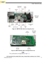


• Two buttons connected to KBI pins
• RS485 output connector
• Female DB9 output connector
• Bottom view (see
Figure 1-2
):
• RS485 transceiver
• RS232 transceiver
• µSD card connector
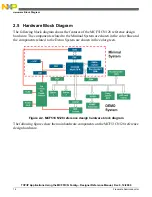
2.4 Connection Between Minimal System and Demo System
Features
The following figure shows how the MCF51CN128 reference design hardware is divided
into a Minimal and Demo system.
A set of zero
Ω
resistors that connect both these systems are present and visible at the top
and bottom layers on the MCF51CN128 reference design hardware. Disconnecting these
registers isolate the Minimal system from the Demo system.
Figure 2-1. Board showing Minimal and Demo system
TCP/IP Applications Using the MCF51CN Family—Designer Reference Manual, Rev. 0, 12/2009
15
Freescale Semiconductor
Chapter 2 Hardware Description


