Chapter 2 Button & LED
62
28
29
30
31
}
}
return
0
;
}
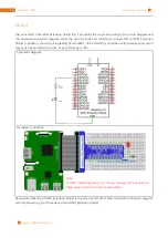
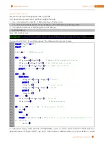
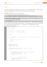
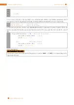
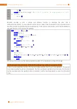
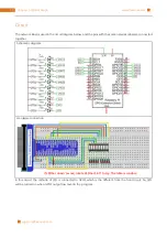
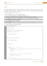
In the circuit connection, LED and Button are connected with GPIO17 and GPIO18 respectively, which
correspond to 0 and 1 respectively in wiringPI. So define ledPin and buttonPin as 0 and 1 respectively.
#define ledPin 0
//define the ledPin
#define buttonPin 1
//define the buttonPin
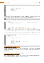
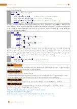
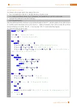
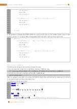
In the while cycle of main function, use digitalRead(buttonPin) to determine the state of Button. When the
button is pressed, the function returns low level, the result of “if” is true, and then turn on LED. Or, turn off
LED.
if
(
digitalRead
(
buttonPin
)
==
LOW
){
//button has pressed down
digitalWrite
(
ledPin
,
HIGH
);
//led on
printf
(
"led on...\n"
);
}
else
{
//button has released
digitalWrite
(
ledPin
,
LOW
);
//led off
printf
(
"...led off\n"
);
}
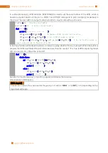
About digitalRead():
i n t digitalRead (int pin)
;
This function returns the value read at the given pin. It will be “
HIGH
” or “
LOW
”(1 or 0) depending on the
logic level at the pin.
Summary of Contents for Ultimate Starter Kit
Page 1: ...Free your innovation Freenove is an open source electronics platform www freenove com ...
Page 117: ...117 Chapter 9 Potentiometer RGBLED www freenove com support freenove com Hardware connection ...
Page 155: ...155 Chapter 14 Relay Motor www freenove com support freenove com Hardware connection OFF 3 3V ...
Page 173: ...173 Chapter 16 Stepping Motor www freenove com support freenove com Hardware connection ...
Page 239: ...239 Chapter 22 Matrix Keypad www freenove com support freenove com Circuit Schematic diagram ...
Page 240: ...Chapter 22 Matrix Keypad 240 www freenove com support freenove com Hardware connection ...

