background image

18

Inspect and tighten all parts of the exercise cycle reg-
ularly. Replace any worn parts immediately. 

To clean the exercise cycle, use a damp cloth and a
small amount of mild soap. 

IMPORTANT: To avoid

damage to the console, keep liquids away from
the console and keep the console out of direct
sunlight.

CONSOLE TROUBLESHOOTING

If the console display becomes dim, the batteries
should be replaced; most console problems are the
result of low batteries. See assembly step 5 on page
7 for replacement instructions. If the handgrip pulse
sensor does not function properly, see step 5 on page
15. 

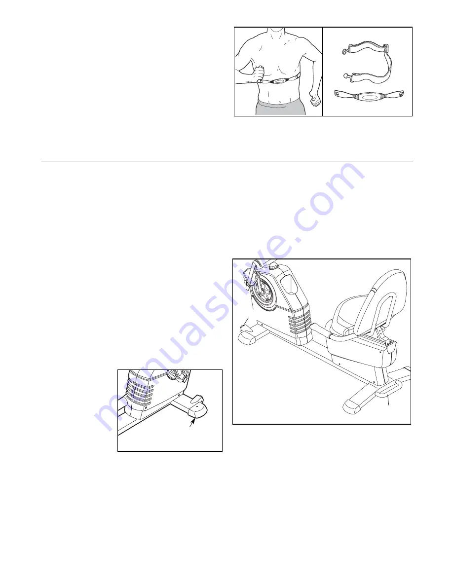
HOW TO LEVEL THE EXERCISE CYCLE

After the exercise
cycle has been
moved to the loca-
tion where it will
be used, make
sure that the ends
of both front stabi-
lizer are touching
the floor. If the
exercise cycle
rocks slightly dur-
ing use, turn one or both of the leveling feet under the
front stabilizers until the rocking motion is eliminated.

HOW TO MOVE THE EXERCISE CYCLE

To move the exercise cycle, hold the handle on the
rear stabilizer and carefully lift it until the exercise
cycle can be moved on the front wheels. Carefully
move the exercise cycle to the desired location and
then lower it.

Handle

Wheel

Leveling

Foot

MAINTENANCE AND TROUBLESHOOTING

THE OPTIONAL CHEST PULSE SENSOR

The optional chest pulse sensor provides hands-free
operation and continuously monitors your heart rate
during your workouts. 

To purchase the optional

chest pulse sensor, contact the store where you
purchased the exercise cycle.

Summary of Contents for R5.7

Page 1: ...Decal Visit our website at www freemotionfitness com Model No SFEX80907 0 Serial No Write the serial number in the space above for reference QUESTIONS If you have questions or if parts are damaged or missing PLEASE CONTACT THE STORE WHERE YOU PURCHASED THIS PRODUCT If you are unable to contact the store call toll free 1 866 799 8946 Mon Fri 8 a m 5 p m MST ...

Page 2: ... DRAWING 22 ORDERING REPLACEMENT PARTS Back Cover FREEMOTION is a registered trademark of ICON IP Inc WARNING DECAL PLACEMENT The warning decals shown here have been applied in the locations shown If a decal is missing or illegible call the telephone num ber on the front cover of this manual and request a free replacement decal Apply the decal in the location shown Note The decal may not be shown ...

Page 3: ...ot be used by persons weighing more than 350 lbs 159 kg 8 The pulse sensor is not a medical device Various factors including the user s move ment may affect the accuracy of heart rate readings The pulse sensor is intended only as an exercise aid in determining heart rate trends in general 9 Wear appropriate exercise clothes while exercising do not wear loose clothes that could become caught on you...

Page 4: ...ise cycle offers an impressive array of features to let you enjoy this healthful exercise in the convenience and privacy of your home For your benefit read this manual carefully before you use the exercise cycle If you have questions after reading this manual please see the front cover of this manual To help us assist you note the product model number and serial number before contacting us The mod...

Page 5: ...ame 1 in the same way 15 54 1 1 55 55 54 17 ASSEMBLY Assembly requires two persons Place all parts of the exercise cycle in a cleared area and remove the pack ing materials Do not dispose of the packing materials until assembly is completed In addition to the included tools assembly requires your own Phillips screwdriver and adjustable wrench As you assemble the exercise cycle use the drawings bel...

Page 6: ...ame 1 Locate the wire tie see the inset drawing in the Upright Tie the lower end of the wire tie to the Wire Harness 43 and to the Pulse Wire 51 Next pull the upper end of the wire tie upward out of the top of the Upright Then untie and discard the wire tie Tip Avoid pinching the Wire Harness 43 and the Pulse Wire 51 during this step Attach the Upright 2 to the Frame 1 with an M10 x 63mm Bolt Set ...

Page 7: ...e tabs on the battery covers and remove the battery covers Next insert four batteries into the Console Make sure that the batteries are oriented as shown by the diagram inside the battery compartment Then reattach the battery covers The Console 4 can also be operated with a regu lated 6 volt DC 2 amp power supply not included To purchase a power supply contact the store where you purchased the exe...

Page 8: ... person holds the Console 4 near the Handlebar 39 connect the console wire har ness to the Wire Harness 43 Next connect the console pulse wire to the Pulse Wire 51 Tip Avoid pinching the Wire Harness 43 and the Pulse Wire 51 during this step Insert the excess wire downward into the Upright 2 Attach the Console 4 to the Handlebar 39 and the Upright with four M4 x 16mm Round Head Screws 80 2 39 7 4 ...

Page 9: ...ur M6 Washers 75 as shown Tip Start all four Round Head Screws before you tighten any of them 9 11 75 75 81 81 60 9 10 Attach the Backrest 8 to the Backrest Frame 60 with three M6 x 38mm Button Screws 67 and three M6 Washers 75 Tip Start all three Button Screws before you tighten any of them 10 60 75 75 8 75 67 67 ...

Page 10: ...he Left Pedal Adjust the strap on the Right Pedal not shown in the same way 12 13 Make sure that all parts are properly tightened before you use the exercise cycle Note After assembly is completed some extra parts may be left over Place a mat beneath the exercise cycle to protect the floor 11 Push the seat handle down Pull the Seat Carriage 41 towards the back of the exercise cycle until it stops ...

Page 11: ...adjust the seat push down on the seat handle slide the seat to the desired position and then pull up on the han dle to lock the seat in place HOW TO ADJUST THE UPRIGHT The upright can be adjusted to the position that is the most comfortable for you To adjust the upright first raise the upright so that it is not resting on the upright knob Next turn the upright knob clock wise or counter clockwise ...

Page 12: ...ercise The console also features the new iFIT Interactive Workout System The iFIT Interactive Workout System enables the console to accept iFIT cards containing workouts designed to help you achieve specific fitness goals For example lose unwanted pounds with the 8 week Weight Loss workout iFIT workouts control the resistance of the pedals while the voice of a personal trainer coaches you and moti...

Page 13: ...corner of the display will show the distance that you have pedaled in miles or kilome ters The center of the display will show the resistance level of the pedals for a few seconds each time the resistance level changes To view the approximate number of calories that you are burning per hour and the approximate number of calories that you have burned during your workout press the Display button You...

Page 14: ...move your hands excessively or to squeeze the metal contacts tightly For optimal performance clean the metal contacts using a soft cloth never use alcohol abrasives or chemicals to clean the contacts 6 Turn on the fan if desired The fan has high low and auto speed settings when you select the auto mode the speed of the fan will automatically increase or decrease as you increase or decrease your pe...

Page 15: ...nce of the pedals will then change As you exercise you will be prompted to keep your pedaling pace near the target pace setting for the cur rent segment When an upward pointing arrow appears in the display increase your pace When a downward pointing arrow appears decrease your pace When no arrow appears maintain your current pace IMPORTANT The target pace settings are intended only to provide moti...

Page 16: ...rip pulse sensor continu ously during heart rate workouts however you should hold the handgrip pulse sensor frequently for the workouts to operate properly Each time you hold the handgrip pulse sensor keep your hands on the metal contacts for at least 30 seconds 5 Begin pedaling to start the workout Heart rate workout 1 is divided into 40 one minute segments Note For a shorter workout stop exercis...

Page 17: ...ired See step 6 on page 15 8 When you are finished exercising the console will turn off automatically See step 7 on page 15 HOW TO USE AN IFIT WORKOUT 1 Press any button on the console or begin ped aling to turn on the console See step 1 on page 14 2 Insert an iFIT card and select a workout To use an iFIT workout insert an iFIT card into the iFIT slot make sure that the iFIT card is oriented so th...

Page 18: ...een moved to the loca tion where it will be used make sure that the ends of both front stabi lizer are touching the floor If the exercise cycle rocks slightly dur ing use turn one or both of the leveling feet under the front stabilizers until the rocking motion is eliminated HOW TO MOVE THE EXERCISE CYCLE To move the exercise cycle hold the handle on the rear stabilizer and carefully lift it until...

Page 19: ...our goal is to strengthen your cardiovascular system you must perform aerobic exercise which is activity that requires large amounts of oxygen for prolonged periods of time For aerobic exercise adjust the intensity of your exercise until your heart rate is near the highest number in your training zone WORKOUT GUIDELINES Warming up Start with 5 to 10 minutes of stretching and light exercise A warm ...

Page 20: ...illes Stretch With one leg in front of the other reach forward and place your hands against a wall Keep your back leg straight and your back foot flat on the floor Bend your front leg lean forward and move your hips toward the wall Hold for 15 counts then relax Repeat 3 times for each leg To cause further stretching of the achilles tendons bend your back leg as well Stretches Calves achilles tendo...

Page 21: ...abilizer Endcap 49 1 Foam Grip 50 2 Flange Screw 51 1 Pulse Wire 52 4 M8 x 50mm Button Screw 53 1 Pillow Block 54 6 M8 x 16mm Button Screw 55 14 M8 Split Washer 56 1 Seat Rail Endcap 57 18 M4 x 16mm Screw 58 2 M8 Jamnut 59 4 Small Snap Ring 60 1 Backrest Frame 61 1 Upright Cover 62 1 M10 x 63mm Bolt Set 63 4 Wheel Bushing 64 1 M4 x 12mm Bright Screw 65 1 Stop Block 66 2 Front Stabilizer Endcap 67 ...

Page 22: ...7 57 84 84 26 57 84 13 57 84 84 6 5 74 14 57 57 5 6 84 75 10 9 11 77 77 77 77 81 55 55 55 75 75 55 10 41 71 71 78 78 78 59 59 49 79 79 79 78 79 67 35 81 60 57 57 EXPLODED DRAWING A Model No SFEX80907 0 R1007A ...

Page 23: ...32 50 33 30 29 31 73 73 72 72 21 21 4 80 7 2 15 19 66 54 17 55 63 63 69 58 83 64 22 22 43 47 51 24 33 28 50 46 20 20 56 62 62 65 82 82 84 68 70 70 70 76 76 76 76 72 72 72 57 61 12 34 36 57 37 57 57 72 44 44 42 80 80 18 25 57 45 85 EXPLODED DRAWING B Model No SFEX80907 0 R1007A ...

Page 24: ...elp us assist you be prepared to provide the following information when contacting us the model number and serial number of the product see the front cover of this manual the name of the product see the front cover of this manual the key number and description of the replacement part s see the PART LIST and the EXPLODED DRAWING near the end of this manual ...

Reviews: