TPA600 Rev170623
1
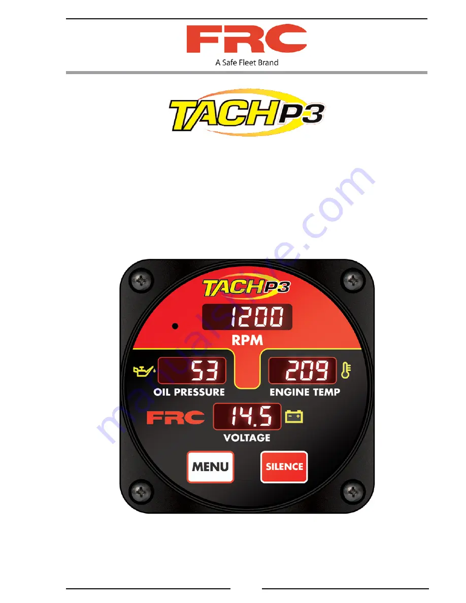
ENGINE MONITORING DISPLAY
MODEL: TPA600
Document Number:
XE-TPA6PM-R0A
FIRE RESEARCH CORPORATION
www.fireresearch.com
26 Southern Blvd., Nesconset, NY 11767
TEL 631.724.8888 FAX 631.360.9727 TOLL FREE 1.800.645.0074
Page 1: ...23 1 ENGINE MONITORING DISPLAY MODEL TPA600 Document Number XE TPA6PM R0A FIRE RESEARCH CORPORATION www fireresearch com 26 Southern Blvd Nesconset NY 11767 TEL 631 724 8888 FAX 631 360 9727 TOLL FREE 1 800 645 0074 ...
Page 2: ...INSTALLATION 6 Install Display Module 6 Install Buzzer 6 OPERATION 8 Transmission Temperature 8 Engine Hours 8 PROGRAMMING 10 Program Access 10 WIRING 12 Connectors and Cables 12 List of Tables and Figures Table 1 Error and Fault Warning Codes 9 Table 2 Program Functions 11 Figure 1 Controls and Indicators 5 Figure 2 Display Module Mounting Dimensions 7 Figure 3 Wiring 12 ...
Page 3: ... battery voltage During normal operation warning messages are displayed as they occur The Engine Monitoring Display receives input information form the J1939 CAN bus Features Non Multiplexed Display Means No Flickering Digital Engine RPM Oil Pressure and Coolant Temperature Displays Battery Voltage Display with Low and Over Voltage Warnings Automatically Adjusts to 12 or 24 Volt System Programmabl...
Page 4: ...and program features OIL PRESSURE Display Shows the engine oil pressure in bright red 0 4 digits ENGINE TEMP Display Shows engine coolant temperature in bright red 0 4 digits Shows transmission temperature when selected VOLTAGE Display Shows the battery voltage in bright red 0 4 digits Whenintheinformationscrollmodethisdisplayshowssystemandoptionsinformation MENU Button The MENU button is used to ...
Page 5: ...TPA600 Rev170623 5 Figure 1 Controls and Indicators RPM Display ENGINE TEMP Display VOLTAGE Display MENU Button SILENCE Button OIL PRESSURE Display ...
Page 6: ...and cables before drilling holes Refer to Figure 2 for layout and dimensions 2 Drill a 1 25 inch diameter hole 3 Drill four holes clearance or tapped for 10 32 mounting screws 3 Place display module in position and secure with screws 4 Connect cable at rear of the module Refer to Wiring section Install Buzzer Abuzzer is supplied with the Engine Monitoring Display Install the buzzer close to the co...
Page 7: ...TPA600 Rev170623 7 Figure 2 Display Module Mounting Dimensions 0 7 4 2 2 0 4 2 1 25 Diameter Hole Mounting holes are clearance or tapped for 10 32 screws 3 5 3 5 ...
Page 8: ...ng that sounds when a monitored input exceeds the set warning level Silencing Audible Alarm All audible alarms can be cancelled by pressing the SILENCE button Pressing the SILENCE button does not change the visual warning Transmission Temperature When the transmission temperature is available on the J1939 CAN bus and the program code P07 is enabled press the MENU button to show it on the ENGINE TE...
Page 9: ...ning Codes DISPLAY DESCRIPTION E01 No Engine Data Received E04 Oil Pressure Problem E07 Engine Temp Problem F01 High Battery Voltage F02 Low Battery Voltage F03 High Transmission Temperature F04 Low Oil Pressure F07 High Engine Coolant Temperature ...
Page 10: ...on to change the digit 4 Repeat step 3 and enter the password code 2222 Result When a correct password code is entered P 0 1 shows in the RPM display 5 Press the SILENCE button to scroll through the program P codes 6 Press and hold the MENU button for three seconds to enter the programming mode to view and change parameter settings 7 While the parameter or value is flashing press and hold the MENU...
Page 11: ... 1 Low battery voltage warning engine off Set Value 11 7 23 4 VDC P07 Transmission temperature enable disable Select yes enabled MENU button is pressed to show temp no disabled yes P08 High transmission temperature warning Set Value 300 F P09 2 Battery voltage source Select bus voltage is read from J1939 CAN bus loc voltage is read from the module input pins bus Notes 1 Module automatically detect...
Page 12: ...toring Display Connectors and Cables The Engine Monitoring Display receives engine RPM oil pressure coolant temperature and transmission temperature data over the J1939 CAN bus from the ECM 6 Pin Connector Cable Pin Wire Color Description 1 Red 12 24 VDC 2 Black Ground 3 White J1939 CAN 4 Green J1939 CAN 5 Blue Buzzer 6 Brown Buzzer Pin 1 6 Pin Plug ...