


DF4000 Rev0204
28
WIRING
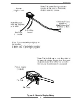
Figure 8. Primary Display Wiring
Note:
Connect the black ground wire
(pin 2) to battery negative (–) or a
good chassis ground (the chassis
ground should have a resistance less
than 1 ohm to the battery negative).
DF4000 Connector
Pin
Signal Description
1
Power 9 - 30 VDC
2
Ground
3
Flow Sensor 5 VDC
4
Flow Sensor Ground
5
Flow Sensor Signal
6
N/C
7
Datalink CAN Low
8
Datalink CAN High
Red Wire
9 - 30 VDC
Black Wire
Ground
5 VDC
Output
Signal
Ground
1
5
8
4
Primary
Display
Note
: Minimum
wire size for power
is 18 AWG.
To Flow
Sensor


