FRC Insight DF4000 Manual Download Page 16

DF4000 Rev0204

16

OPERATION

On power-up the flowmeter will be in the normal operating mode. Flow rate

information from a flow sensor or from the datalink interface is processed and displayed.
Operator input is necessary only when using the totalizing function or accessing
program information.
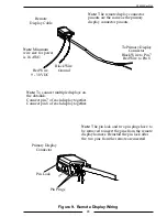
Datalink Interface

The FRC datalink interface is standard on all flowmeters and provides a way of

connecting multiple display modules on a shared data bus. The DF4000 (digital
flowmeter) and FP4000 (pressure gauge/flowmeter) series display modules can operate
as independent displays or they can be interconnected to provide remote displays, the
display of flow through multiple discharges (summing), and the display of total flow
for multiple discharges (accumulation). (Refer to Figure 6.)

Primary Display Module

Primary displays are programmed with the module function 

Pri

. A primary display

receives input from the pressure transducer and flow sensor. When it is programmed
with Id 0 it will not output information on to the datalink. When it is programmed
with Id 1 to Id 99, it will provide information (via the datalink) to remote, summing,
and accumulator displays.

Remote Display Module

Remote displays are programmed with the module function 

SLA

 (slaved to a

primary). A remote display must be programmed with the same ID number as a primary
display. It will receive information for the display of flow rate from the primary display
over the datalink. All program code features are programmed independently of the
primary display. No calibration is necessary on a remote display.

Summing Display Module

Summing displays are programmed with the module function 

SU

. A summing

display will show the actual flow rate for all primary displays on the datalink except
for those with Id 0.

Accumulator Display Module

Accumulator displays are programmed with the module function 

ACC

. An

accumulator display will show total accumulated flow for all primary displays on the
datalink except for those with Id 0. The number shown in the display will be x 100
scale.

Note:

 A single display module can be used for both summing and

accumulation. Program it as a summing display, when the 

TOTAL

 button

is pressed it will show total accumulated flow for all primary displays on
the datalink.

Summary of Contents for Insight DF4000

Page 1: ...DF4000 Rev0204 1 DIGITAL FLOWMETER MODEL DF4000 Insight Series FIRE RESEARCH CORPORATION fireresearch com 26 Southern Blvd Nesconset NY11767 TEL 631 724 8888 FAX 631 360 9727 TOLL FREE 1 800 645 0074...

Page 2: ...GENERAL DESCRIPTION 6 Components 6 Controls and Indicators 7 INSTALLATION 8 Install Display Module 8 Install Flow Sensor 10 OPERATION 16 Datalink Interface 16 Program Features 18 Total Button 18 PROG...

Page 3: ...7 Figure 2 Display Module Mounting Dimensions 9 Figure 3 Flow Sensor Location Guidelines 11 Figure 4 Saddle Clamp Installation 13 Figure 5 Weldment Installation 15 Figure 6 Typical Datalink 17 Figure...

Page 4: ...le identification and program access The digital display is used to show stored data or operator inputs when a selectable mode is accessed In the display module identification mode the digital display...

Page 5: ...Dimensions Height 3 25 Inches Width 3 26 Inches Depth 2 4 Inches Datalink Protocol J1939 CAN Flow Sensor Type Paddlewheel with Brass Housing for Saddle Clamp or Weldment Mount Stainless Steel Housing...

Page 6: ...e factory installed All controls and indicators are located on the front of the display module Refer to Controls and Indicators Paddlewheel Flow Sensor The flow sensor provides an input signal to the...

Page 7: ...by using the MODE button The MODE button is used along with the TOTAL button to enter and input data in the program access mode See Programming section for more information Total Button The TOTAL but...

Page 8: ...n be checked if modules are swapped Note It is recommended to have the flowmeter mounted close to the associated discharge valve 1 Measure and mark mounting location for display module panel cutout an...

Page 9: ...DF4000 Rev0204 9 Figure 2 Display Module Mounting Dimensions Panel Cutout 25 95 C L 2 75 Diameter Hole Tap or Drill Clearence Hole for 10 32 Screw 2 7 3 25 2 72 3 26 1 65 2 13...

Page 10: ...tions are outlined in Figure 3 When the sensor is mounted after an area in the plumbing that tends to increase water stream turbulence a valve increase in pipe diameter etc it is critical that steps a...

Page 11: ...ipe diameter When mounting the sensor before a valve or an elbow the length L must be at least equal to the pipe diameter When mounting the sensor after the pipe diameter is reduced the length L must...

Page 12: ...and is not meant to be removed 3 Place saddle clamp over hole with sensor housing centered 4 Tighten saddle clamp nuts until the gasket makes a good tight seal 5 Insert flow sensor into sensor housin...

Page 13: ...for removal installation of the connector C B A Pipe Size Dimensions Sch 40 A B C 2 5 5 3 9 2 9 2 5 5 5 3 9 2 8 3 5 9 3 9 2 8 3 5 6 8 4 3 2 8 4 6 8 4 3 2 8 5 8 4 3 2 8 Measurements are in inches Senso...

Page 14: ...on the pipe centerline Refer to Figure 5 4 Set sensor housing to dimension A in Figure 5 Make sure the alignment tab is centered on the pipe as shown it can be on upstream or downstream side 5 Screw o...

Page 15: ...er cap is tightened make sure the sensor rim flat spot does not disengage from the alignment tab and allow the flow sensor to rotate Pipe Size Dimension Sch 40 A 1 5 1 95 to 1 80 2 1 95 to 1 80 2 5 1...

Page 16: ...it is programmed with Id 1 to Id 99 it will provide information via the datalink to remote summing and accumulator displays Remote Display Module Remote displays are programmed with the module functio...

Page 17: ...unction Pri ID Number Id 1 FLOWMETER INSIGHT Function Pri ID Number Id 4 FLOWMETER INSIGHT Function SLA ID Number Id 1 FLOWMETER INSIGHT Function SLA ID Number Id 2 FLOWMETER INSIGHT Function Pri ID N...

Page 18: ...et the totalized flow to 0 if the totalizer reset function is set to YES Display Total Flow When the TOTAL button is pressed and released the digital display will show the total accumulated flow and t...

Page 19: ...the MODE and TOTAL buttons are used to enter a program code Once a program code is entered the MODE button is used to select the digit to be changed and the TOTAL button is used to change the digit or...

Page 20: ...Module Function To change use program access code 313 PROGRAM ACCESS MODE DISPLAYS Mode Selected Ready for program code to be entered Entering Code Ready for first digit of code to be entered Code Ent...

Page 21: ...flash Each time the MODE button is pressed the number will scroll up by 1 Set the first digit to the number desired 3 Press the TOTAL button The second digit shown in the display will flash Each time...

Page 22: ...2 ID Number Factory programmed value Options 0 to 99 This code will allow the datalink identification ID number for the display module to be set The display can be programmed with an ID number between...

Page 23: ...Increments by 1 at Flow Rates Below Program Value 312 ID Number 0 to 99 313 Module Function Pri SLA SU ACC 315 High Flow Warning 0 to 9999 0 Disabled 316 Low Flow Warning 0 to 9999 0 Disabled 317 Tota...

Page 24: ...display module Flow total will reset to 0 when the TOTAL button is pressed and held When the totalizer reset is set to no the flow totals will accumulate and will not reset to 0 even when power is of...

Page 25: ...An invalid program code has been entered Re enter program code when the digital display resets Error Code E204 There is no signal from the sensor This code will only be displayed when in a calibratio...

Page 26: ...code 321 Result The digital display will show the flow rate with the last digit flashing 2 Flow water through the discharge at the flow rate selected for the calibration point Ensure a constant press...

Page 27: ...at the flow rate selected for the calibration point Ensure a constant pressure is maintained to obtain a steady flow rate 3 Press the MODE button Result The display will show a flow rate with the last...

Page 28: ...e a resistance less than 1 ohm to the battery negative DF4000 Connector Pin Signal Description 1 Power 9 30 VDC 2 Ground 3 Flow Sensor 5 VDC 4 Flow Sensor Ground 5 Flow Sensor Signal 6 N C 7 Datalink...

Page 29: ...e to be removed to insert the pins from the remote display harness Reinstall the pin lock after the two pins from the remote are inserted Note To connect multiple displays on the datalink Connect pin...

Page 30: ...t No Description 1 DF 4000 X X Insight Kit GPM DF 4010 X X Insight Kit LPM X X Pipe Size 2 DF 4000 DM Insite Display Module GPM 3 DFC XX Primary Display Cable XX Cable Length In Feet 4 MF 15P Paddlewh...

Page 31: ...DF4000 Rev0204 31 This page intentionally left blank...

Reviews: