background image

Fraser Anti-Static Techniques, Scotts Business Park, Bampton, Devon EX16 9DN, UK

T + 44 (0) 1398 331114      F + 44 (0) 1398 331411      E [email protected]      W www.fraser-antistatic.com

18

NEOS 30 OEM-DM-Iss.2

7. OPERATION & CONTROL

Remote DISABLE input

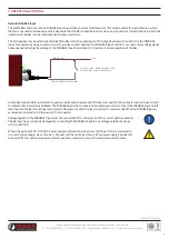
The NEOS Bars feature a remote DISABLE input signal (Grey or Green/Yellow wire). This may be useful for installations in which 
the Bar is not used continuously and it is desirable that the Bar should be inactive when not required, or in installations in which the 
operation of the Bar is to be interlocked with other machinery.

The HV supplies may be externally disabled (Standby mode) by applying any DC voltage between 3 V and 28 V to the DISABLE 
input, for example by using an external switch or relay contact between the DISABLE input and 24 V, or a logic-level voltage signal. 
Subsequently reducing the voltage at the DISABLE input to lessthan 0.5 V restores normal operation of the Bar.

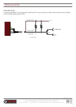
GREY OR GREEN / YELLOW WIRE

BROWN WIRE

+24V

SWITCH CLOSED - BAR IN STANDBY MODE

SWITCH OPEN - NORMAL OPERATION

In Standby mode the Bar internal HV supplies are disabled, the status LED flashes red, and the OK output is inactive (open circuit) 

to indicate that ionisation is disabled. The DISABLE signal has a weak internal pull-down resistor, thus if the DISABLE signal is left 
disconnected the Bar should operate normally. However, for added noise immunity it is recommended that the DISABLE input is 
externally connected to 0 V (blue wire) if not required.

Voltage applied to the DISABLE input must not exceed 28 V DC, and must be of the correct positive polarity. 
The Bar may be permanently damaged by connecting the DISABLE input to any voltage outside the range 
of 0 V to 28 V DC.

Where the optional SPX - 0724 AC Power Supply has been ordered ensure the Power Unit is connected to 
3 wire AC mains supply, Live + N Ground, and that extra Earth wire from power supply is bonded to 
Ground. With this optional supply an interface cable is required to access the remote monitor feature.


D

TITLE

REVISION

MATERIAL

SCALE

DRAWING No.

5

6

C

DO NOT SCALE

SHEET 1 OF 1 

B

A

1

2

3

C

IF IN DOUBT - ASK

4

5

B

6

A

D

1

2

THIRD

ANGLE

3

PROJECTION

ALL SHARP EDGES AND CORNERS TO BE REMOVED
MACHINING TOLERANCES UNLESS OTHERWISE STATED

4

SPECIFICATION AND SYMBOLS TO BS308

ONE DECIMAL PLACE
TWO DECIMAL PLACES
0-100mm
100-500mm
ABOVE 500mm

SURFACE FINISHES TO BS1134

±0.1mm
±0.01mm
±0.25mm
±0.4mm
±0.75mm

A3

SCOTTS BUSINESS PARK

BAMPTON, DEVON

 EX16 9DN

WWW.FRASER-ANTISTATIC.COM 

TEL: 44-(0) 1398 331114

FAX: 44-(0) 1398 331411

1:5

Summary of Contents for NEOS 30 OEM

Page 1: ...Features 3 Typical Applications 4 Position in the NEOS range 5 Why is it called OEM 6 Differences to standard NEOS 30 7 Performance 02 03 03 05 05 06 07 1 Introduction 2 Safety 3 Use 4 Checking on Del...

Page 2: ...basic operation for all pulsed DC static neutralisation Generally short distances are neutralised with higher frequency for example 50 Hz on the 3014 and 3024F longer distances are neutralised with s...

Page 3: ...ns where the distance between the charged material and the Bar changes significantly during the manufacturing process A large part of this market will be where winders and unwinders are used High prod...

Page 4: ...NEOS 30 OEM DM Iss 2 3 TYPICAL APPLICATIONS Unwinders Winders and unwinders are found on hundreds of different types of production machinery Unwinder The NEOS Bar is 200 mm from the surface of a new r...

Page 5: ...requirements see NEOS Distributor Manual The NEOS 30 OEM can be used for all of these distance ranges Please see Performance section for more details NEOS 30 SETTING FOR DISTANCES AN 200 mm 500 mm AL...

Page 6: ...n it flashes to show the operating frequency In all other ways the NEOS 30 OEM is externally the same as the standard NEOS 30 same compact profile half the size of the Simco ThunderION same lengths av...

Page 7: ...ow does the performance of NEOS 30 OEM compare to the intelligent AN and AL Settings This is more difficult to answer because the effectiveness of the AL and AN setting depends on the size of the char...

Page 8: ...sential that you read and understand the complete manual before installing and using this equipment This is important for safety and for warranty cover SECTION 2 TECHNICAL INSTALLATION 1 1 Explanation...

Page 9: ...ide the Bar Ensure the Bar and connecting cable are free from damage prior to installation and check periodically once in use Bar must be switched off before removing or reconnecting the signal cable...

Page 10: ...ng to check bar function remotely Connection to 24 V DC is via a standard M12 5 Pin Connector Connection to 4 20mA current loop signal is via a standard M8 3 Pin connector Not suitable for outdoor use...

Page 11: ...ndustry standard M12 5 Pin female connector Emitters Long life high grade Tungsten LED Green Green Flashing OK Flashing Red Standby Red Fault Red Green Flashing Attention required Status Indication OK...

Page 12: ...not possible to neutralise static electricity where the material is touching another surface or roller ii The Bars must be dry and oil free iii It is important that the emitter pins are not touching...

Page 13: ...OS 30 OEM DM Iss 2 7 OPERATION CONTROL The pin assignment and typical wire colours are given in the table below MALE PIN VIEW 1 3 2 ON BAR FEMALE SOCKET VIEW 3 1 2 ON CABLE Pin Wire Colour Function De...

Page 14: ...OS 30 OEM DM Iss 2 7 OPERATION CONTROL Electrical Using an existing 24 V DC supply the 24 V return must be fitted with 2 5 Amp fuse e g Type 2 5 AT 250 V The 0 V output must be connected to earth DC F...

Page 15: ...ing to the following conditions Condition Ionisation OK White Pin 2 Attention Black Pin 4 Bar powered all OK ACTIVE HV ON ACTIVE connected to 0 V ACTIVE connected to 0 V Bar powered requires attention...

Page 16: ...WIRE WHITE WIRE PLC 2 4 OK ATTENTION MAX 200m A D TITLE REVISION MATERIAL SCALE DRAWING No 5 6 3 C IF IN DOUBT ASK 4 5 B 6 A THIRD ANGLE 3 PROJECTION ALL SHARP EDGES AND CORNERS TO BE REMOVED MACHINI...

Page 17: ...4V IEC 61131 2 Type 2 PLC input or other 24V control system can be obtained using an external pull up resistor to 24V D TITLE REVISION MATERIAL SCALE DRAWING No 5 6 3 C IF IN DOUBT ASK 4 5 B 6 A THIRD...

Page 18: ...is inactive open circuit to indicate that ionisation is disabled The DISABLE signal has a weak internal pull down resistor thus if the DISABLE signal is left disconnected the Bar should operate normal...

Page 19: ...0 OEM Pulse Green Rapid Flash Green Bar State LED State Cause Attention Red Green Alternate Flash Dirty or abnormal conditions Action Clean Bar Check Installation Check Process IONISATION ACTIVE IN TH...

Page 20: ...rformance Our Fraser cleaning kit Part Number 81220 is ideal for use alternatively a toothbrush or nail brush can be used Do not use a wire brush as this could damage the Bar The Bar can be washed wit...

Page 21: ...are normal the status LED will turn GREEN If the status LED does not illuminate GREEN or RED then check the electrical supply If the electrical supply is OK then check the connecting cables for damag...

Page 22: ...cture Description Part No 81193 3 m cable M12 female bare ends Straight socket 81194 5 m cable M12 female bare ends Straight socket 81195 7 5 m cable M12 female bare ends Straight socket 81196 10 m ca...

Page 23: ...w fraser antistatic com 23 NEOS 30 OEM DM Iss 2 12 SPARE PARTS ACCESSORIES Item Picture Description Part No NEOS PSU Universal AC DC power supply 100 250 V AC 24 V DC output Fitted with 1 5 m of cable...

Reviews:

Related manuals for NEOS 30 OEM