Franklin Electric SubDrive Connect Plus SDCP-CEN0723 Quick Start Manual Download Page 10

QUICKSTART GUIDE

FE Connect Mobile App for SubDrive Connect Plus

10

FE Connect Mobile App for SubDrive Connect Plus

The SubDrive Connect Plus companion app is an intuitive way to wirelessly configure and control your VFD. 
It provides features such as:

Simple, application-based setup for quick and easy startup

Create templates for fast configuration of multiple drives

MultiDrive set up and control

Informational dashboard for visual monitoring of system performance

Mobile control mode for easy Hand mode operation

In-app troubleshooting with fault time and date logging

Email system logs directly to FE support

Wireless drive firmware updates from your phone

Search for FE Connect in your mobile device’s app store. In the search results, locate the 

FE Connect Sub

-

Drive C

 app and install it. Once installed, the app icon is named 

SubDrive Plus

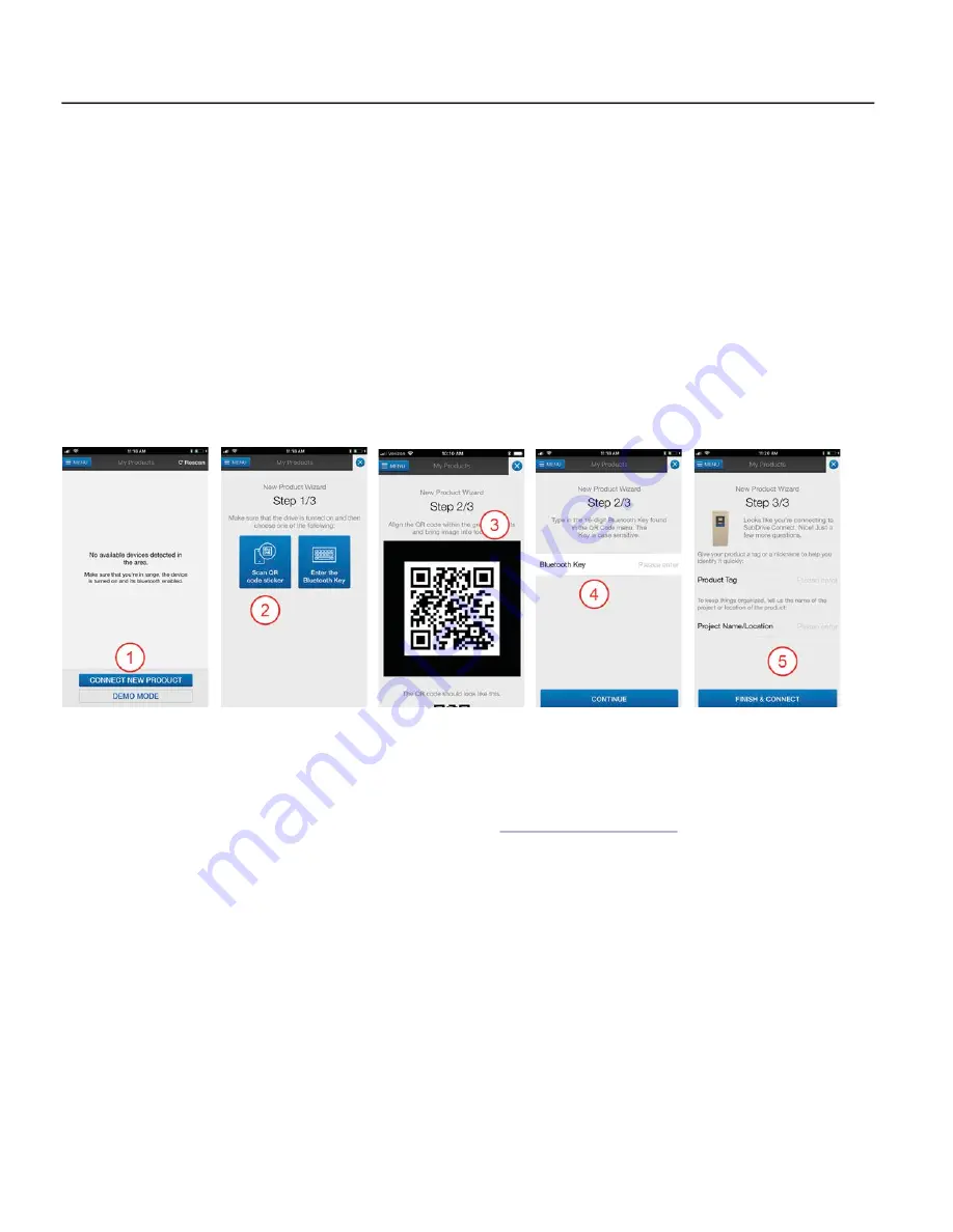
Setup Bluetooth Connection

After installing the SubDrive Plus app, use the following procedure to connect to the drive:
1.

From the Home screen, tap “Connect New Product.”

2. On the 

New Product Wizard

 screen, tap either 

Scan QR Code

 or 

Enter the Bluetooth Key

.

3. If using the scanning tool, center the QR code on the drive in the screen. The code is displayed on the 

VFD display and on a sticker to the right of the display. Refer to 

“Menu Navigation” on page 7

.

4. If using the Bluetooth key, (also available onscreen) enter it in the box provided.
5. Enter a Name and Location to identify the drive within the app.
6. Tap Finish & Connect to complete the connection.

Using the Mobile App

To communicate with a SubDrive Connect Plus that has been paired with the app:
1.

On the 

My Products

 screen, tap the name of the drive to connect to the device and enter the Dashboard.

2. Tap the 

MENU

 button to for a list of options.

3. Tap 

Setup

 to change VFD settings.

IMPORTANT:

 We recommend that the app be updated before going to installation site. Open the app when 

connected to the internet to get the latest update.

Summary of Contents for SubDrive Connect Plus SDCP-CEN0723

Page 1: ... to improper handling installation or environment Install in a location where temperature is within the range of product rating Mount VFD vertically top up for proper heat dissipation Do not mount VFD in direct sunlight or near other heat sources Do not install in corrosive environments Install away from direct sunlight and extreme temperatures or humidity Installation of non approved screening ma...

Page 2: ...AWG 20 to AWG 2 31 in lbs 3 5 Nm AWG 16 to AWG 2 0 50 in lbs 5 5 Nm Risk of damage to VFD or malfunction can occur Follow all wire routing and grounding instructions carefully Inductive currents caused by parallel wiring or close proximity between high voltage and control wiring can cause unexpected behaviors Do not run input power and motor wires in the same conduit Do not run motor wires from mu...

Page 3: ...ck on the dV dt filter 3 J10 Jumper location two jumpers here 4 J11 Jumper location two jumpers here Ground Connections 1 Make sure a service entrance ground rod is properly installed and connected 2 An input power ground wire from the supply panel must be connected to the drive 3 A dedicated output ground wire from the drive must be connected to the motor Motor and ground wires must be bundled to...

Page 4: ...tions marked Ground Red W Yellow V and Black U For drives that include a dV dt filter motor connections are made at the terminal block on the left side of the dV dt filter 3 at right In this case the terminals are marked Ground Red U Yellow V and Black W NOTE Relay terminals accept wire sizes from 12 to 26 AWG and should be tightened to a torque of 3 in lbs 0 35 Nm Do not use power tools to tighte...

Page 5: ...ode 5 PT100 1000 Connector for external RTD temperature sensor I Positive connection for excitation current circuit for two three and four wire PT100 PT1000 RTD sensors V Positive connection for voltage sensing circuit for two three and four wire PT100 PT1000 RTD sensors I V Negative connections for the excitation and voltage sensing circuits for two three and four wire PT100 PT1000 RTD sensors 6 ...

Page 6: ...ms building up pressure in a controlled manner The Pipe Fill feature is disabled when the switch is in the off down position The Pipe Fill feature is enabled when the switch is in the on up position NOTE Additional configuration of the Pipe Fill feature is available in the SubDrive Connect Plus mobile app Analog Output Selection DIP SW1 Position 4 Use this switch AO to select the signal to be repe...

Page 7: ...ressure is set using the adjusting screw on the sensor itself The Sys tem Response screen is displayed next for Pressure Sensor use Sensor Range This is only configurable when the sensor type is transducer This setting scales system operation to the installed transducer The range is 100 to 300 with a default setting of 200 PSI When changing the setting changes in 10 PSI increments Setpoints Drive ...

Page 8: ...and repeat as necessary Deep Set In cases where the pump is set very deep run the system at open discharge to pump the well down and observe carefully that an Underload is detected properly If the system does not trip as it should adjust to a higher sensitivity setting Underload Off Time This setting determines how long the drive will wait before attempting to run after an Underload event The defa...

Page 9: ...running RUN or stopped STOP 3 When using a pressure transducer the system displays the current sys tem pressure in PSI When using a standard pressure sensor the system displays the current motor speed in Hz When running in HAND mode the system displays the keypad frequency setpoint 4 When using a pressure transducer in AUTO mode the motor speed is displayed at the lower left of the screen In HAND ...

Page 10: ...th Connection After installing the SubDrive Plus app use the following procedure to connect to the drive 1 From the Home screen tap Connect New Product 2 On the New Product Wizard screen tap either Scan QR Code or Enter the Bluetooth Key 3 If using the scanning tool center the QR code on the drive in the screen The code is displayed on the VFD display and on a sticker to the right of the display R...

Page 11: ...s replace drive F7 Auto Overheated Drive High ambient temperature Direct sunlight Obstruction of airflow Fan blocked or inoperable ambient above 122 F 50 C direct sunlight Replace fan or relocate drive as necessary Remove debris from fan intake exhaust F9 Manual Internal PCB Fault A fault was found internal to drive Contact Technical Service F12 Auto Overvoltage High line voltage Internal voltage ...

Page 12: ...ation of this equipment requires detailed installation and operation instructions provided in this manual for use with this product Read entire manual before starting installation and operation End User should receive and retain manual for future use Keep safety labels clean and in good condition High voltages capable of causing severe injury or death by electrical shock are present in this unit T...

Reviews: